
Do 217E-5
The Do 217 was built on the success of the Do 17 series and was essentially a scaled up development of the basic design. Initially the design was not all that successful, suffering from instability and its performance fell below requirements. The RLM was also unsatisfied with its ability to carry larger weapons and new systems and equipment then under development. After working through numerous changes, the prototype for the E series introduced a substantially deepened fuselage and BMW 801 engines which solved most of the problems the RLM was concerned about. The E-1 version was relatively successful in early operations but experience dictated additional defensive armament as well as armor protection for the crew. The E-2 version introduced the power operated turret. The E-3 added additional machine gun positions as well as armor protection for the pilot and crew. The E-4 version differed only in respect to the engine configuration and the E-5 added the wing carriers and radio equipment to operate the Henschel Hs 293 stand off missile. The first operational use of these was against allied destroyers in the Bay of Biscay on August 25, 1943.
The Kit
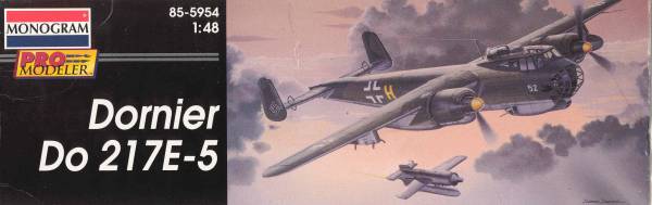
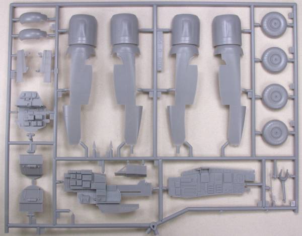
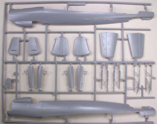
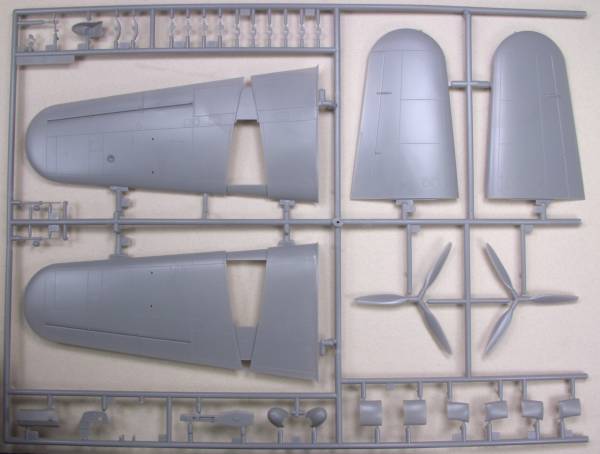
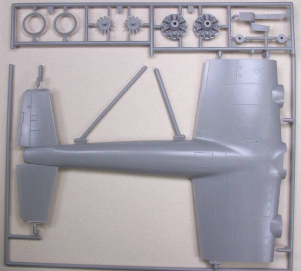
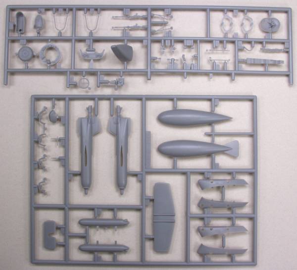
The Promodeler Do 217E-5 comes in a rather large box with nice artwork on the front. Inside the box are seven sprues molded in a light gray color and one sprue of clear parts. The clear parts were bagged separately. The parts have a smooth glossy finish and the surface detail is recessed. The panel lines are typical for the scale and uniform. The surface of the major airframe parts was defect free except for some sink marks on the side of the upper rear fuselage. There are numerous ejector pin marks. Most are in locations that will be difficult to see such as inside the gear bays. There are some on the landing gear struts as well but those look easy to clean up. One typical location, the insides of the gear door are free of them. The cockpit features nice detail even without any after market goodies and will look like a museum piece with them. about the only thing lacking is harnesses and belts for the seats. There is structural detail in the gear bays. The flight control surfaces are all fixed. The engine detail is nice but only partially modeled, however once install they are pretty much invisible anyway. The engine fans are a bit thick and have a parting seam all the way round. The landing gear is nicely modeled and even includes molded in brake lines. For external stores the kit supplies a Hs 293 radio controlled missile and an external fuel tank. The missile is a complete kit in itself. Altogether there are 135 part in gray, see photos below.
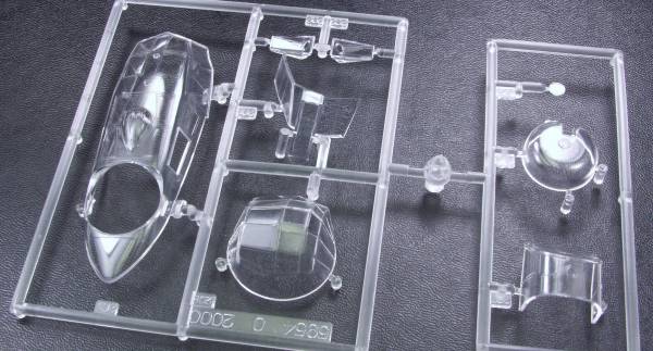
The clear parts are thin and clear with raised frame lines. altogether there are 8 clear parts for a kit total of 142 parts. See photo below.
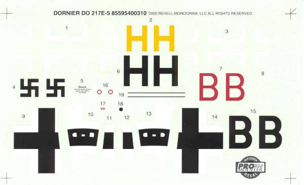
The decals are thin and in register and include markings for two two aircraft, both from KG 100 operating in the Bay of Biscay circa 1943 but with different paint schemes. Only a few stencil marking are supplied. See photo below.
The instructions are a typical Promodeler booklet 16 pages long. It does not include any prototype photos as some Promodeler booklets do but there are no surviving aircraft to photograph. Page one has history , page two warnings, icons and a paint chart giving color names, RLM numbers and FS numbers. pages three through fourteen are assembly steps and the last two are painting and marking instructions.
After Market Goodies
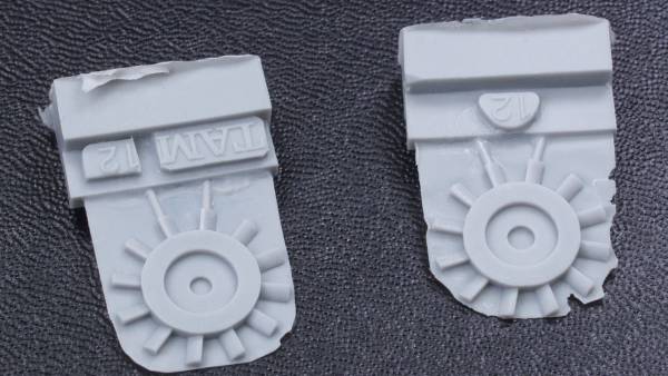
To start off with we have replacement engine fans from Cutting Edge [CEC48335]. The kit fans are overly thick and have a parting line all the way round that is a bear to clean up. These parts are thinner and crisply molded. The flash is thin and is easily removed and clean up is much easier than with the kit parts. The parts are molded in a gray resin and have no pin holes or other surface blemishes. See photo below.
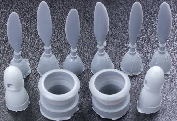
Next up is a props, cowl rings and spinners set from Cutting Edge [CEC48345]. This takes care of some minor discrepancies with the kit parts, the props are of a slightly wider cord the spinners are a little different in shape and length and have the recess in the tip missing on the kit parts and the cowl rings sit a little more proud on the cowling. The spinners and cowl rings are very cleanly molded. The parts are molded in a light gray resin. The props showed some flash and a couple of them had minor surface blemishes that will need either filled or sanded down. While the changes are minor they do make a notable difference in the look of the kit. See photo below.
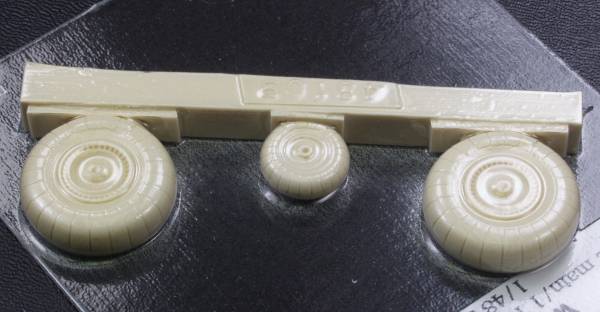
Also available is a resin wheel set from True Details [48109]. These really don't have much to offer over the kit parts except no parts to glue together and no seam to worry about, the trade off being they need to be cut off the pour blocks and cleaned up. Some sources report that the kit wheels are too narrow but this set doesn't correct that issue and in the end I may not use them as it would be easier to widen the width of the kit parts. See photo below.
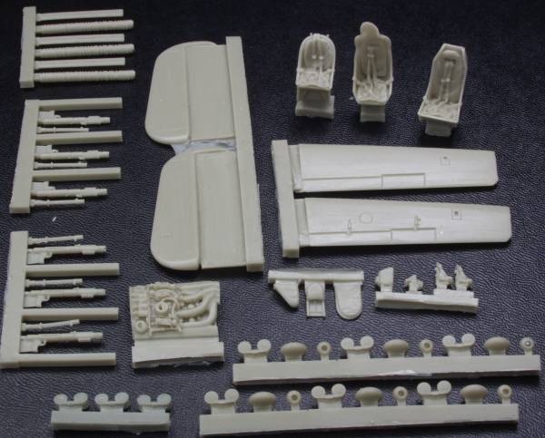
The resin parts are molded in a tan colored resin. The rudders and elevators didn't seem to me to offer much more than the kit parts save from being separated so they can be mounted in different positions. The surface texture was a little rough in spots but there were no short shots or pinholes visible. The elevators looked a little short when compared to the molded in place elevators on the kit. The set includes six hand held machine guns with separate ammo cases, spent casing collection bags and ball mounts. They are nicely detailed but do have some flash to clean up. There are also three spent casing chutes and three ammo belts as well. The engine detail that gets used if decide to open the engine cowl up seems a bit shallow detail wise to my eye anyway. Probably the best of the resin parts are the three seats. There are two different pilots seats, both with molded harness and belts and a replacement radio operators seat with the same and a much higher level of detail than the kit parts. There are also a couple different armor plates to be used with the pilot seats. The other items included are a replacement lens assembly for the bomb sight, two rudder pedal assemblies and a pilots gun sight. Altogether there are 54 resin parts. See photo below.
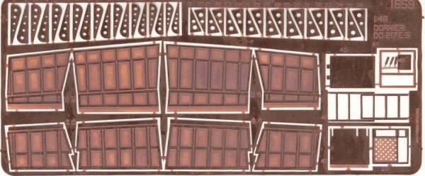
The final piece in the kit is a photoetch fret containing the parts for the dropped flaps and wing structure exposed when the flaps are extended, the cover for the cowling if you chose to open it and detail parts for the crew hatch with ladder. These parts are etched from a very heavy copper .012" thick so they have a very good depth to the etched areas. See photo below.
The instructions are printed on an 8 1/2" x 11" page printed on both sides with written instructions on one side and diagrams on the other. Even if you don't use all the parts on this kit a lot of the parts can be used on other Luftwaffe bombers.
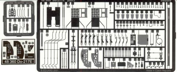
Eduard has a detail set, photoetch, [48360], that has all those little goodies you can't live without, see photo below.
And lastly a mask set from Black Magic [CEBM 48485]
Conclusions
This is an excellent kit that builds up into a nicely detailed model right out of the box with little in the way of fit issues. It has also been well catered to by the after market folks with the exception of decals. Highly recommended
Links to kit build or reviews
A review / build of the model can be found here and here.
References
Warplanes of the Third Reich by William Green
Dornier Do 217 - 317 - 417 by Manfred Griel
The Build
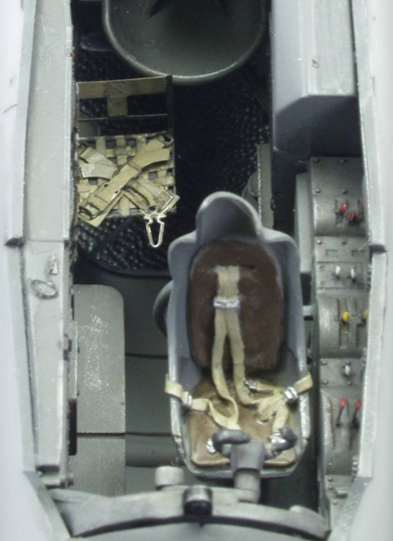
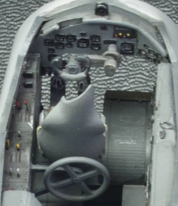
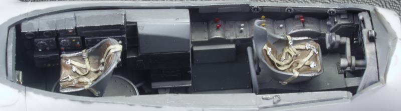
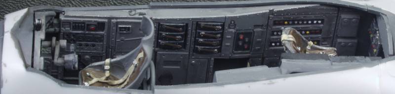
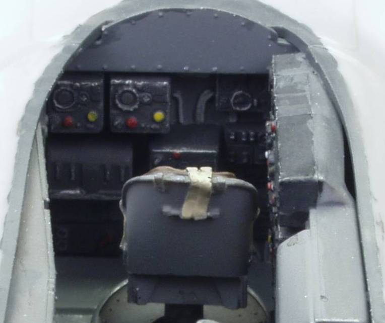
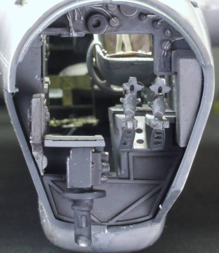
Like most aircraft the build begins with the interior or cockpit and this one was no exception. I used both parts from the Eduard set and the Verlinden set to enhance the cockpit. I chose to use replacement seats for the pilot and radio operator from the Verlinden set and opened one of the jump seats using a seat from the Eduard set. Once the interior was complete to my satisfaction it was given a sludge wash and some highlighting with a silver pencil. When I installed it in the fuselage I found that the fuselage itself had a twist in it and that put me off for some time as I wasn't quite sure how to handle it. In the end I went with a progressive gluing starting on each side at the front and working my way toward the tail. I would line up and glue a section at a time until it was all done and in the end everything pulled out and lined up OK. Below are some photos of the interior after the fuselage went together. I still need to run some brake lines to the rudder pedals but other than that it's about ready for the glazings to be installed.
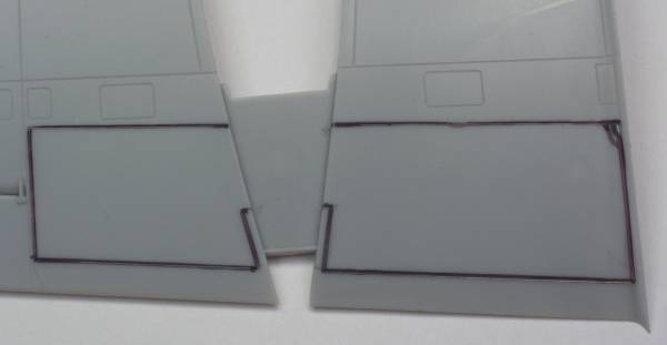
Next I decided to work on the wings, specifically the dropped flaps. For these I needed to remove the flap area from the bottom side of the wings as outlined in the next photo.
I knew that, due to the narrow edge that would be left on the right side, that my normal method of scribing the lines through the plastic would be fraught with danger and sawing looked problematic as well so I decided to try a tool I had never used before at least not on plastic models. The tool in question is called a nibbler. and can be seen below
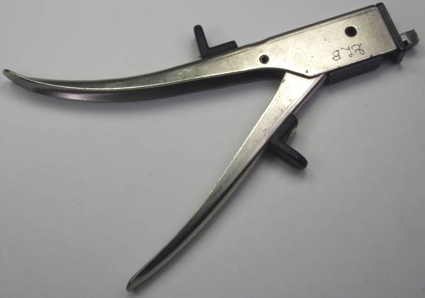
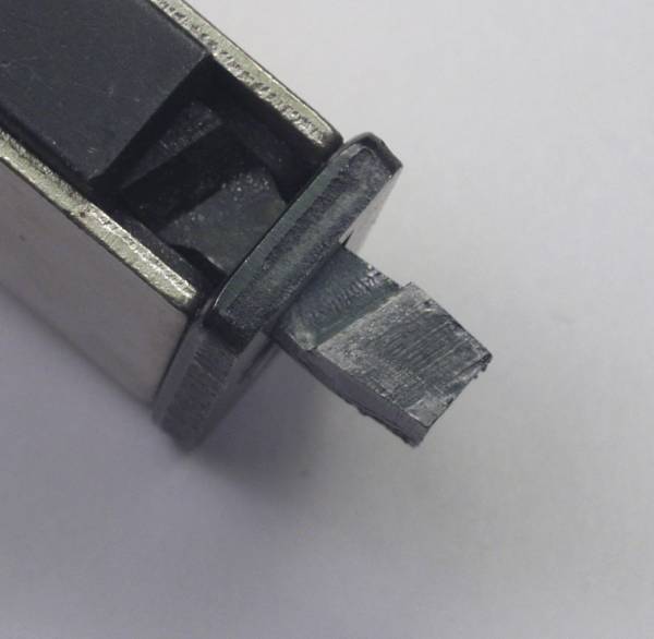
This tool is sold primarily to hobbyists and professionals in the electronics industry and is used for cutting out square holes in panels for slide switches, displays or other controls that require a square hole. They are made for working with light gage steel or aluminum. I purchased mine years ago at Radio Shack but I'm not sure they still sell them but a Google search should turn up some vendors for them. When you squeeze the handle it moves a square shaped punch down against a square die and takes out a rectangular chunk of material. The head is shown below.
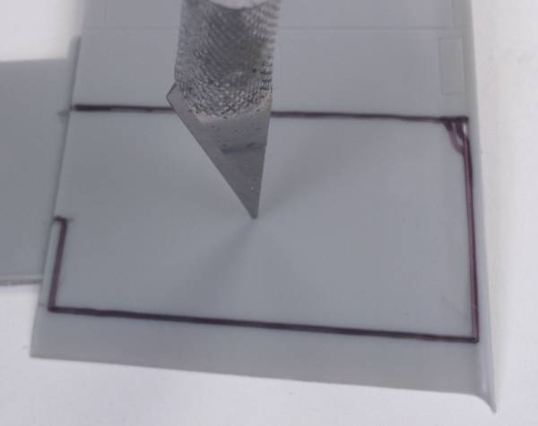
In use one drills a round hole in the area where you need the square hole large enough to pass the punch part through. You then proceed to move the die to the area where you want to remove material and squeeze the handles. This takes a bite out of the material. You repeat this process until all the material is removed. To start I made a hole using my X-acto knife to get it started. Just place the knife tip where you want the hole the pressing down turn the knife and it will cut its way through
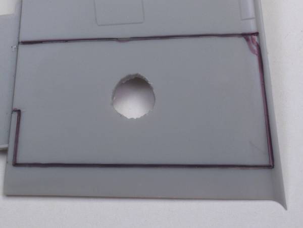
There is a limit to how large of hole you can make and in this case it wasn't large enough. One could have used a large twist drill bit here but I find these tend to be too aggressive in plastic and can grab and tear and do lot of damage. In this case to bring the hole up to size I used another tool not all that common to modeling but handy none the less. This tool is the tapered reamer. Another metal working tool designed to increase the size of a hole if the next size drill is too big. It starts at one end around 1/8" and tapers up to 1/2". It also has the advantage as it only turns as fast as you can turn it you have a great deal of control and it doesn't get hot and melt the plastic as drill bits will do. See below.
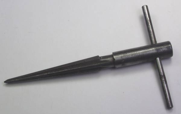
This tool can be purchased most anywhere that sheet metal tools are sold. This tool was then used to enlarge the hole to the size needed. Once this was done the head of the nibbler was inserted and the nibbling begun.
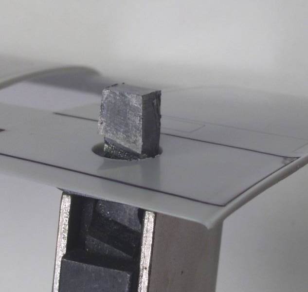
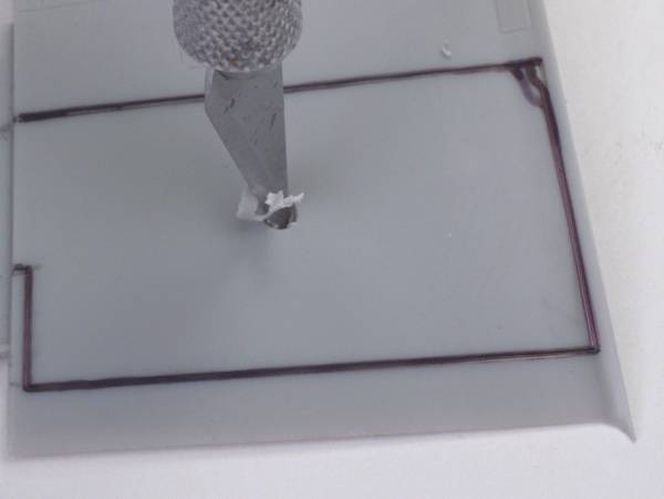
Here is what it looks like after the first bite.
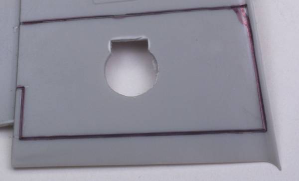
It most be noted that there is a limit to the thickness that will fit under the die head, about 1/8" and that this process works best on soft plastic, if the plastic is brittle the pressure of punching may crack the plastic. After each bite the tool is moved forward and another bite is taken. As shown below it took three bites to get close to the edge where I wanted to be. The tool doesn't have the control necessary to follow the line dead on so I stopped there, rotated the tool 90º and continued nibbling, I just wanted to get close and finish the edges with a file or sanding stick.
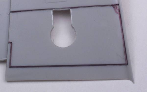
In the next photo I have nibbled to the outer edge and nibbled away some of the interior area. One could just nibble along the periphery but I find it easier to remove some material from the inner area to make it easier to maneuver the tool.
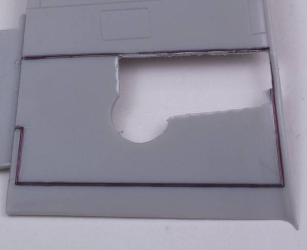
Next photo shows the completed cut away with the edges cleaned up and ready for the next step,
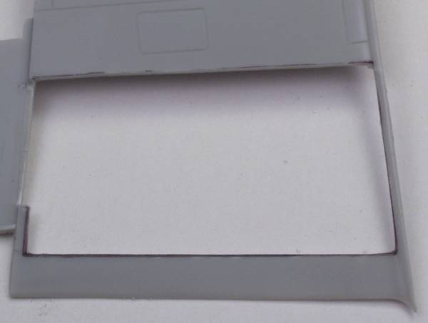
After all four openings had been complete the wing assembly could commence !
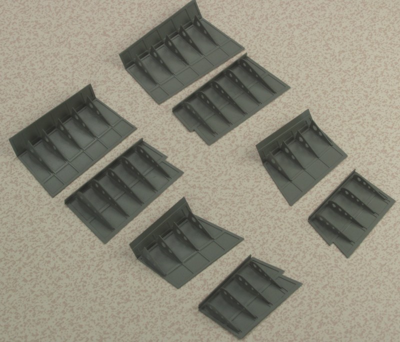
Flash forward nine years and after languishing on the shelf of doom for longer than it should have I finally decided to finish it. This is a very nice kit and I think the only reason it dragged was I decided to do too many new things at once. This was the first kit that I used photo etch and resin parts on and in the end both bogged me down. I got it to the stage shown above and every time I looked at the flap assemblies I cringed. When I finally decided to finish the kit the first thing I did was assemble the flaps and they went together without a fuss. Shown below after painting and before installation in the wings, I didn't want them hanging out during the masking and painting of the airframe. The first and third rows are the flaps and a piece that blanks off the wing interior and the second and third rows are the parts that mount in the wing.
I didn't do any in progress photos after this as it would only show masking and painting. I also had issues with most of the kit supplied decals, perhaps due to their age but I always seem to have issues with silvering when using the newer style German crosses. As a result I made stencils for all the markings except the large under wing crosses, the nose numbers and the swastikas which I got from a generic sheet.
During final assembly I discovered that the time that the kit had spent stuffed in a plastic storage box had caused the wings to develop a dihedral which cause the landing gear to splay outwards. I ended up clamping a straight bar across the top of the wing with spacers under it to push the wing in the opposite direction and applying some heat with a heat gun. I managed to accomplish this with only a few minor issues and was able to complete the kit. The photos below show the final result.
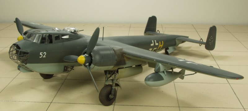
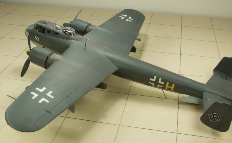
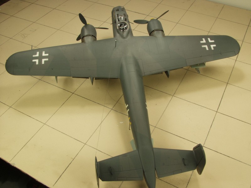
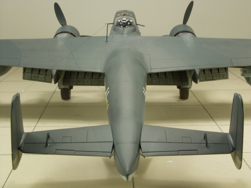
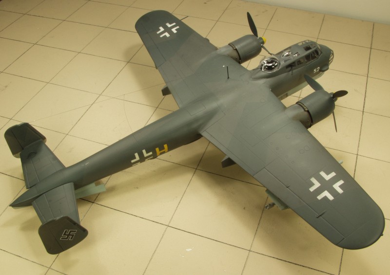
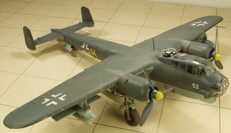
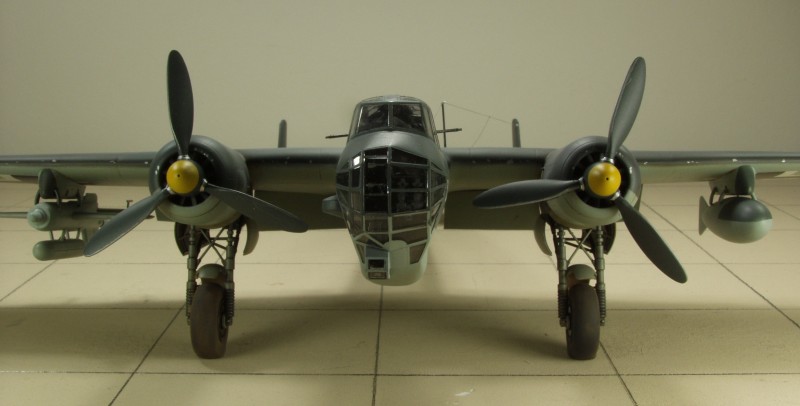
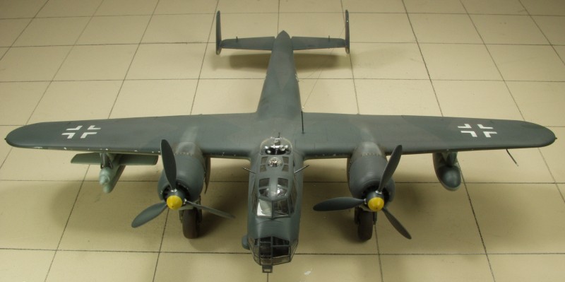
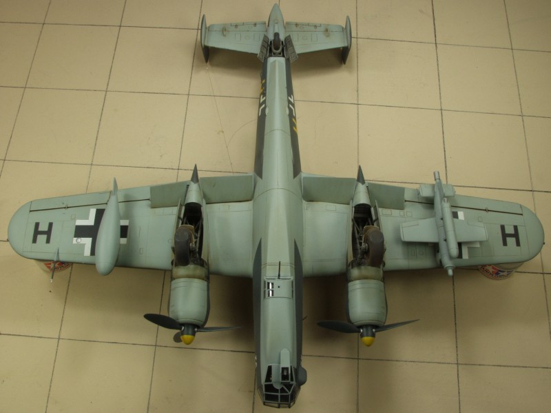
For
a kit that was started almost ten years ago it doesn't look all that
impressive. This was one of the first kits I started back when I
returned to modeling and as such it was the first kit that I
used photo etch and resin parts and the combination of the two that
early on resulted in my setting it aside too many times and eventually
into a box that got gradually buried. This is actually a very nice and
not that difficult of a kit and many of the issues I had with it were
my own doing. If the subject interests you I encourage that you find
and build one.
Updated 11/3/17