
RA-5C Vigilante
. Back in 1967 after graduating from a local two year technical college, I went to work at North American Rockwell's Columbus, Ohio plant. North American Aviation had merged with the Rockwell Corporation to form North American Rockwell. The plant was then producing, among other things, the RA-5C Vigilante. At that time I was already a die hard aviation enthusiast and model builder and found the experience totally fascinating. To get to my work area from where my ride parked (I didn't own a car at the time) I had to walk the entire length of the final assembly line. So every day I could see the progress made on each plane as it made its was down the line. The T-2B Buckeye trainers were also being built in the same building as the Vigi's so I some times took that route as well. At the head of the assembly line was the heavy machining area where the one piece wing skins were milled and machined and I found that fascinating as well. My job itself also has a tie in as I worked with a secret clearance in the antenna assembly area. My job was to build the band 7 passive ECM receiving antenna assembly of which two were used on the Vigi. The department I was in was also responsible for one section of the "canoe" that mounted on the bottom of the fuselage as well as numerous other antennas used on the Vigi. As an aside I also was involved with making some parts for antennas used on the Apollo space capsule and built up a process proving clothes line antenna assembly that was to be used on the then new OV-10 Bronco. The band 7 were mounted one on each side of the fuselage. Part of the bar on the star and bar insignia on the side of the plane crossed the radome on the antenna. As a result of this experience I had held out hopes for years that someone would make a kit in 1/48 and when Trumpeter announced it I could hardly wait.
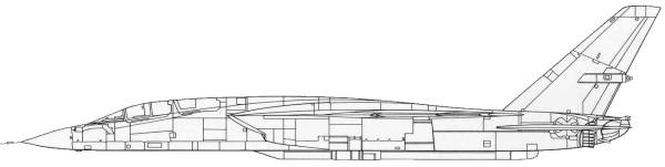
The Vigilante was quite an advanced aircraft for its time and among its many "firsts" was the first use of an airborne digital computer for bomb and navigation computations. It also had the first Bomb-Nav System with an inertial auto navigation coupled to radar and television-sights for check point verification. The Vigilante had the first heads-up display, the first fully integrated auto pilot/air data system for Bomb/Nav weapons release, the first monopulse radar with terrain avoidance features, the first variable inlet using horizontal ramp geometry and the first production fly-by-wire control system.
The Vigilante was originally intended to be a high performance attack aircraft with all weather capability. North American received a letter of intent to build two YA3J-1's in 1956. The Navy wanted a nuclear armed aircraft with Mach 2 capability to replace the AJ Savage, the Lockheed P-2 and the Douglas A-3 Skywarrior. The aircraft made its first flight on August 31, 1956. One unique feature of the Vigilante was its linear bomb bay, basically a tunnel running the length of the rear fuselage between the engines. The bay was equipped with rails, a catapult and stored a nuclear weapon at the forward end. When the weapon was launched a disposable tail cone was released, then the bomb attached to fuel tanks was released. The fuel tanks contained fuel that was consumed prior to reaching the target, thus they were empty when dropped and were designed to stabilize the bomb as it fell to the target. The bay was flexible in that it could carry other systems such as reconnaissance instruments, auxiliary fuel tanks or other special equipment packages. In service however the bomb ejection system never worked very well at least from the accuracy standpoint. While it met the Navy's high performance requirements it could not carry a large enough non-nuclear conventional internal payload to warrant large scale production and the Navy soon realized that its strategic role could be best performed by submarine launched missiles.
Despite a nearly trouble free development period the Vigilante was not ordered into mass production until 1959. These were intended to be conventional strike aircraft. The Vigilante's first carrier landing was made aboard the USS Saratoga in July of 1960, bringing the Navy into the Mach 2 world. In the 1960-61 period, the Navy gave up its carrier-based strategic nuclear weapons role and that left the Vigilante without a viable mission. Due to its ability to accurately drop external stores and its speed capabilities a case was made for its existence as a high speed low altitude bomber. The new aircraft would be the A3J-2, later to be known as the A-5B. It incorporated an increased internal fuel load, increased external weapons capabilities, blown leading edge flaps an increased trailing edge flap span, increased engine intake duct capture area and increased performance J79-GE-8 engines. Before the first A3J-2 made its first flight in April of 1962, the A3J-3 was authorized for production with yet another new mission as a high speed reconnaissance aircraft and the A3J-3 became the RA-5C. Eighteen aircraft were built as A-5B's and of these twelve were re manufactured as RA-5C's. Forty-three were built following these and in 1968 the line was reopened and an additional 36 were built bring the total of both new and rebuilt aircraft to 140 delivered to the Navy.
The Kit
I jumped on the presale of this one with both feet. Only when some of the early reviews started coming in was I a little let down. First there were issues with the shape of the frontal part of the fuselage then reports of problems with the bottom seam and finally intake shapes that varied depending on whether the plane was early or late production. This was a bit of an issue as I wanted to build one representative of those that I made parts for. Well thanks to the after market folks these problems have been addressed.
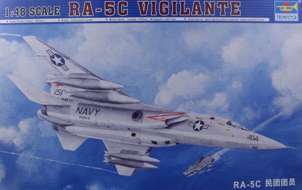
The Trumpeter kit comes in a large heavy top open two part box made entirely out of corrugated cardboard with attractive artwork on the top. Inside the box there are numerous bags of parts as well as a separate flap open box which is designed to float above the rest of the parts and contains bags with the clear parts, the fuselage back end cap and the canoe for the bottom of the fuselage. With the exception of the fuselage halves which are in one bag, all the other bags have two sprues in them. The kit is molded in a medium gray plastic with recessed panel lines are fastener detail. Due to the complexity of the kit I'm going to give a photo by photo analysis of the kit starting with the fuselage shown below.

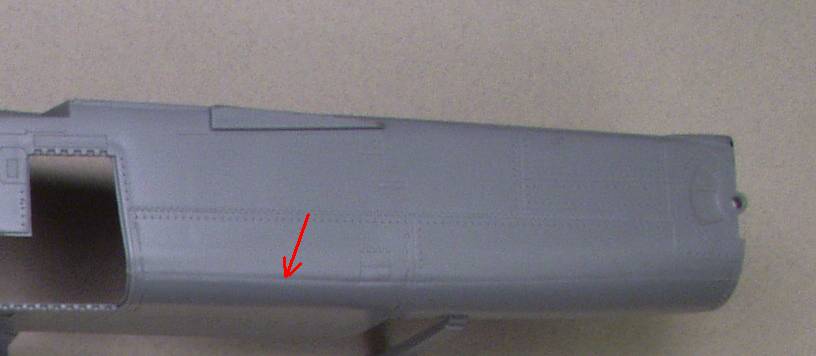
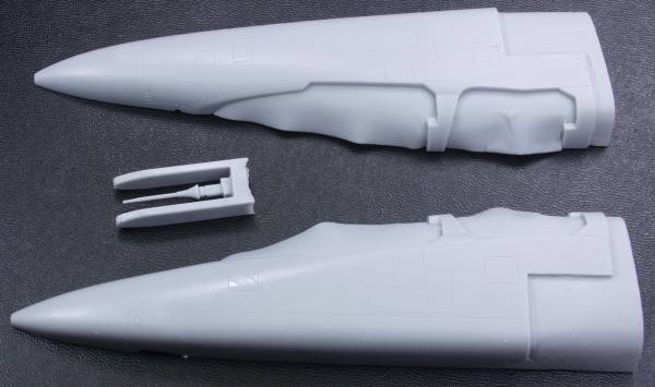
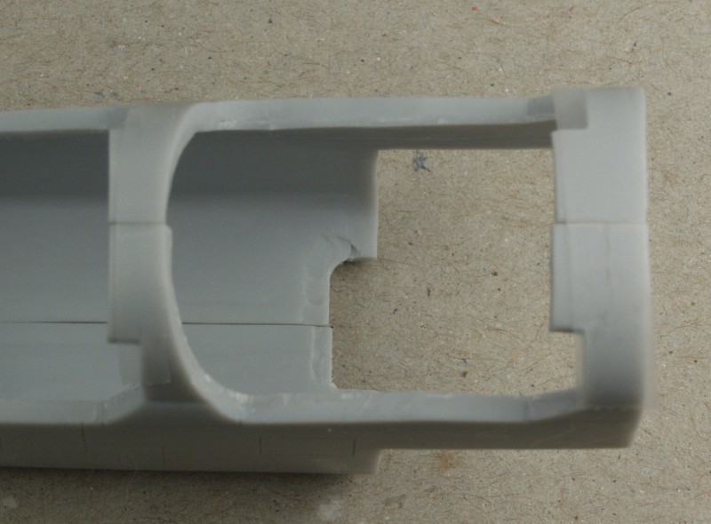
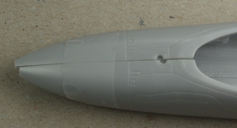
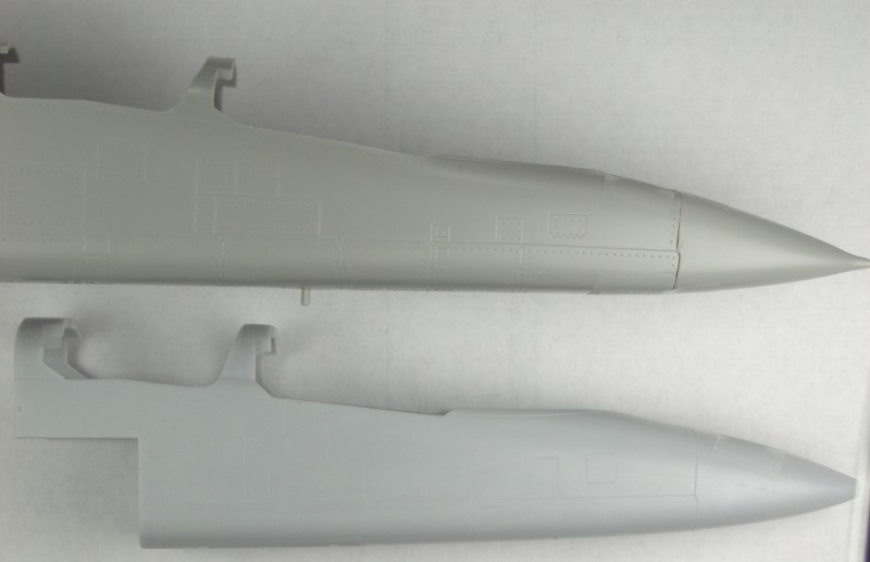
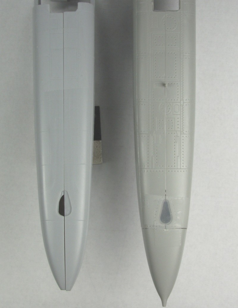
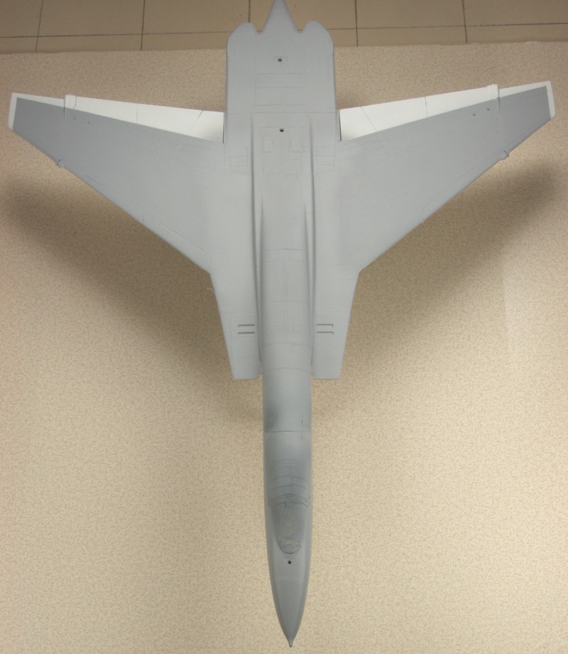
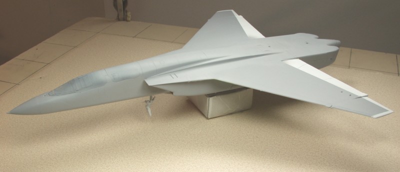
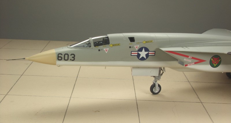
The fuselage halves are a fairly complex part that must have given the mold makers some fits. On both halves there is a seam line that runs from nose to tail. At the nose it is more of a raised line but aft of the gear doors it's more of a depression. This is more pronounced on the port side than the starboard. There is a similar line that starts just aft of the bomb nav cockpit and disappears near the trailing edge of the wing. Other than these marks the fuselage halves are free of other defects and have a light amount of flash. The panel lines are uniform but in my opinion the fastener detail is a bit deep. I suspect it will look better once painted. According to the "experts" the profile of the nose is not correct. Unless you study a lot of photos I don't think it's all that noticeable but if it bugs you a fix will be discussed later in this review. One other problem that manifests itself during assembly is that the long seam on the bottom tends to pucker inward due to lack of support creating a difficult fill job, although this is some what hidden by the canoe on the bottom. A fix is available for this as well and will be covered later. The photo below points out the worst of the mold line.
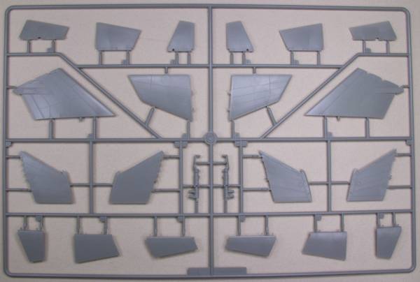
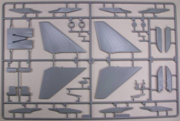
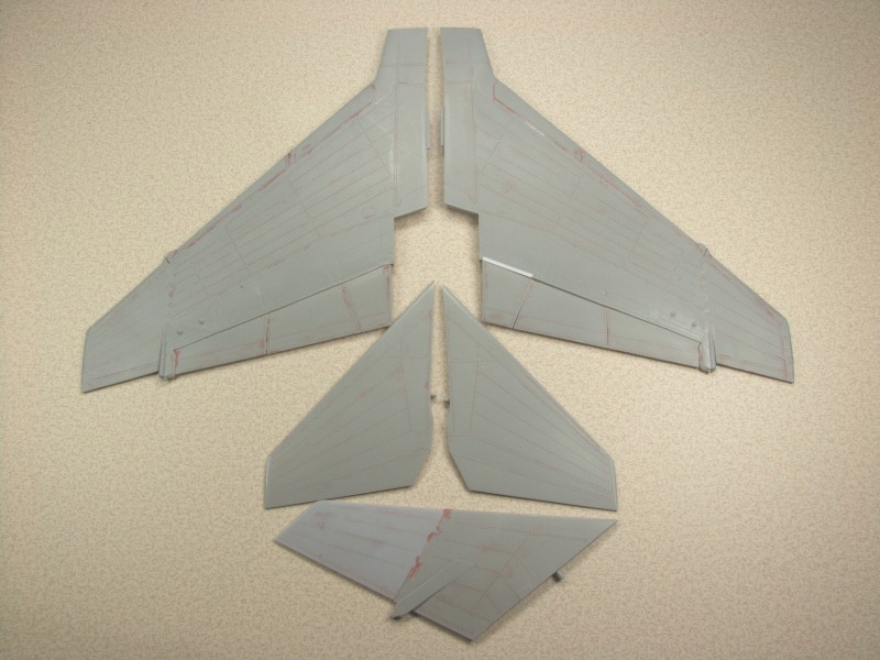
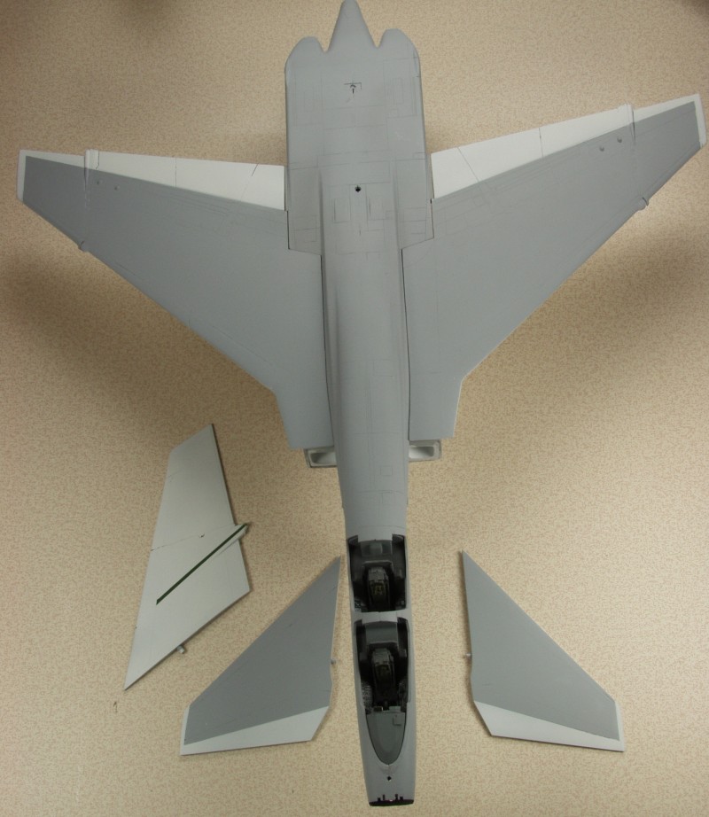
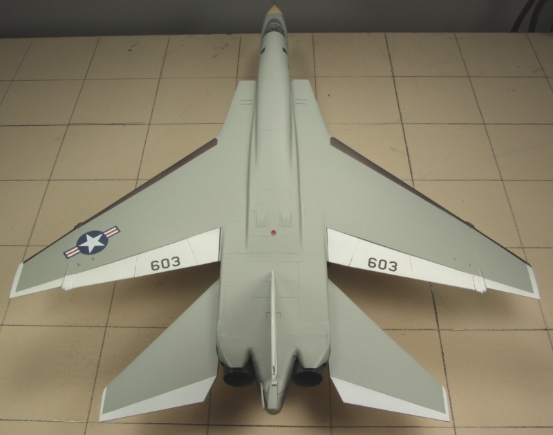
The next two sprues contain the wings, tail, movable control surfaces, wing pylons, flash pods main gear struts and doors and various and sundry pieces. I found no surface defects and no ejector pin marks that will show, not even on the main struts and gear doors. There was little to no flash on the parts and only minimal parting lines on some parts. See below.
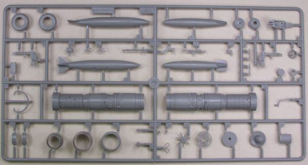
The next two, of which only one is shown as they are duplicates, have the engines, under wing tanks, main wheels and rims and various other small parts. The engines are reasonably well detailed but little of them will be seen when the kit is complete. There was little to no flash on the parts and only minimal parting lines on some parts. See below.
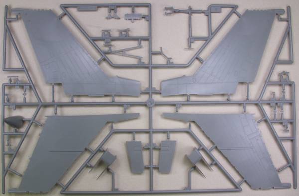
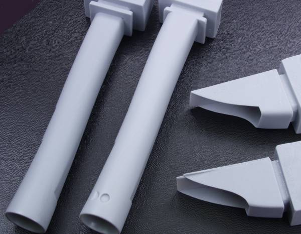
The next sprue has the wing center sections, the intake ramps and numerous other parts including the nose gear strut, nose cone, refueling probe and arrestor hook. The rather delicate ramp side parts were individually wrapped with foam to protect them during shipping. There was little to no flash on the parts and only minimal parting lines on some parts. See below.
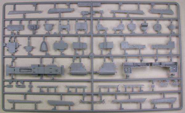
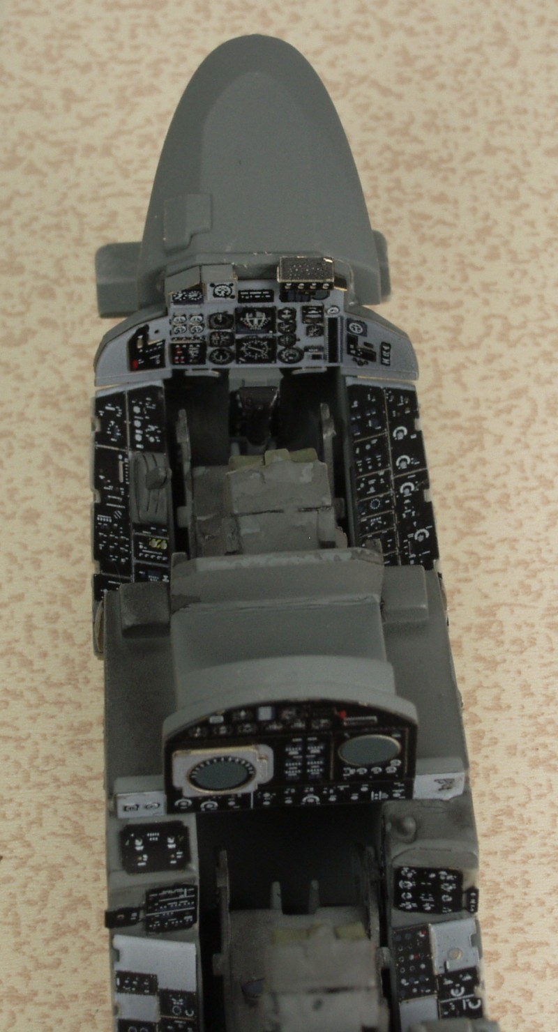
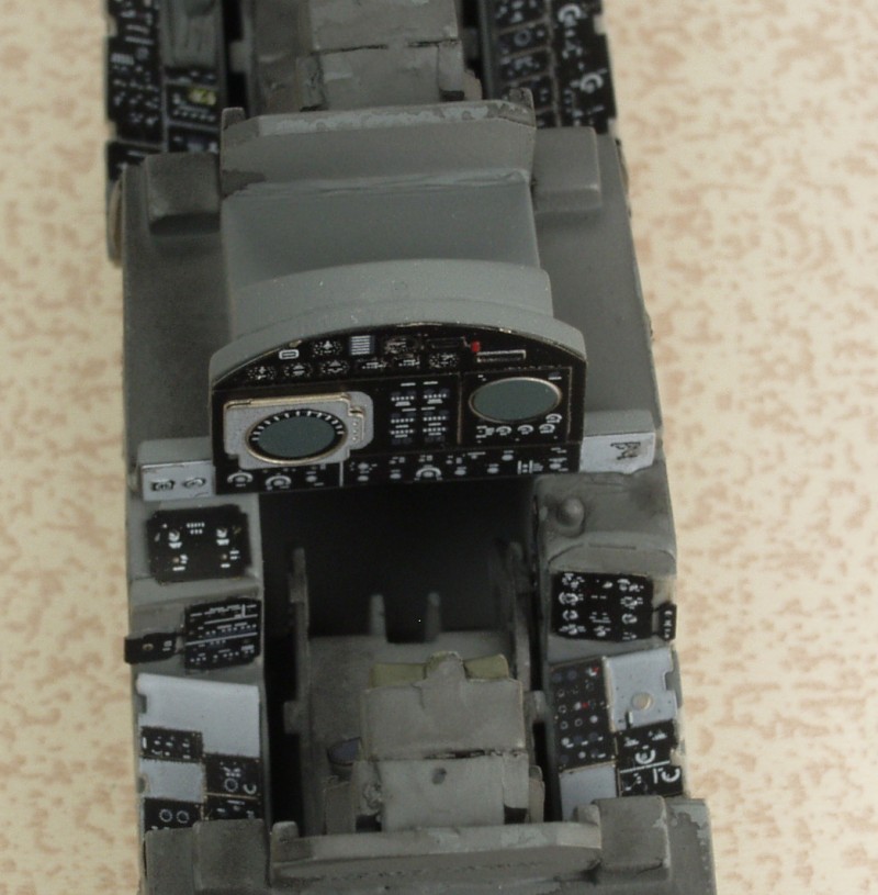
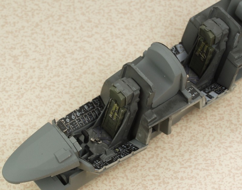
The next sprue has the main gear bay, cockpit parts, slats and more doors, more intake ramp parts and the balance of the miscellaneous parts. The cockpit has a good level of detail. There was little to no flash on the parts and only minimal parting lines on some parts. See below.
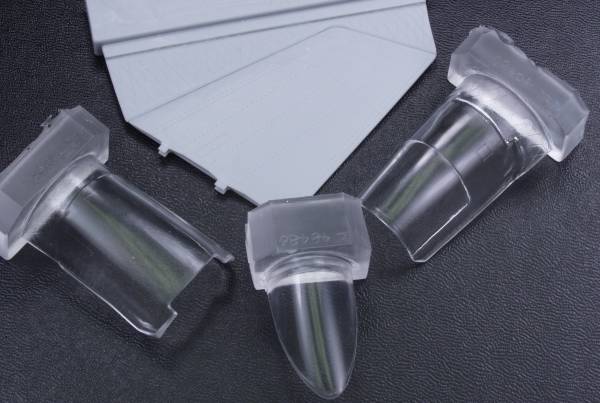
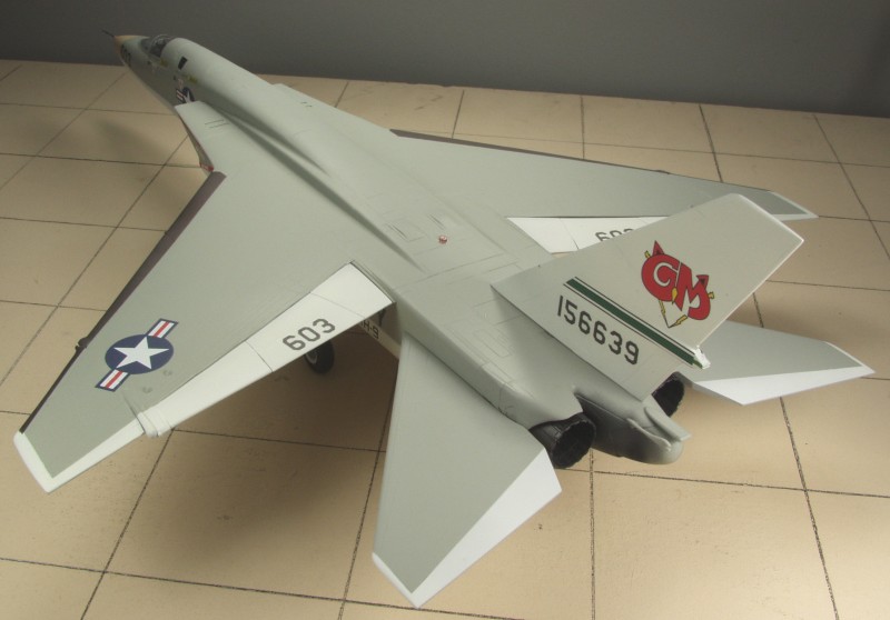
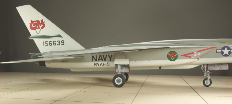
The last two parts were packaged in the box inside the box and each were individually bagged. The tail cone does an excellent job representing the poorly fitting tail cone. On the bomber version this was to be an expendable part that was jettisoned when the bomb was launched out the back. The other part is the so called canoe that fit on the bottom of the plane and could be configured with a variety of reconnaissance devices. See photo below. Assuming I counted correctly there are 209 parts molded in gray.
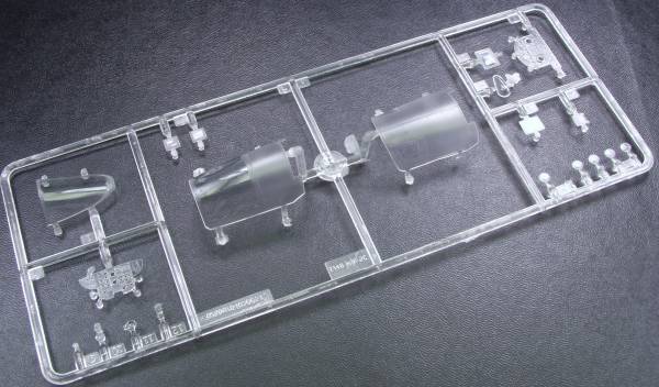
The clear parts are thin and clear with frosted areas where they need to be painted. Included are the pilots and bomb/ nav operators instrument panels. A clear film with instruments is provided to fit behind it. The balance of the clear parts are lens for the flash pods, cameras, landing lights and others. See photo below. There are 20 clear parts bringing the kit total to 229, quite a box full of parts.
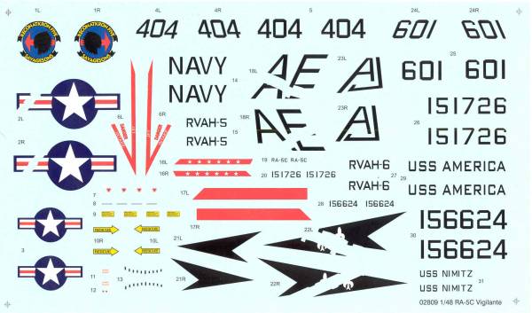
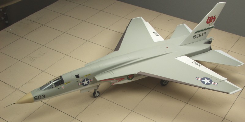
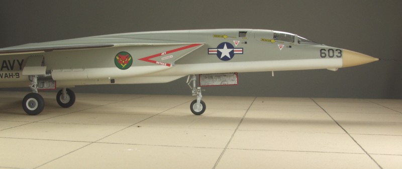
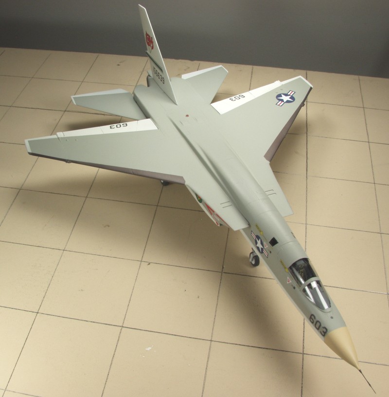
The decals appear thin and are in register. Included are markings for two aircraft. Decals that fit over wing or tail folds are in separate pieces. Most of the most noticeable stencils and warning labels are included. The decals were bagged separately along with the instrument panel films. See below.
The instructions consist of a sixteen page booklet that is stapled together. The front page has a side view of the aircraft, a "read before assembly" dissertation and an icon chart. Page two has a parts map. The balance of the booklet is all assembly. Also included is an 11" x 16" glossy page printed on one side with painting and marking instructions.
After Market Goodies
And now for the part where you take an expensive kit and make it really expensive!
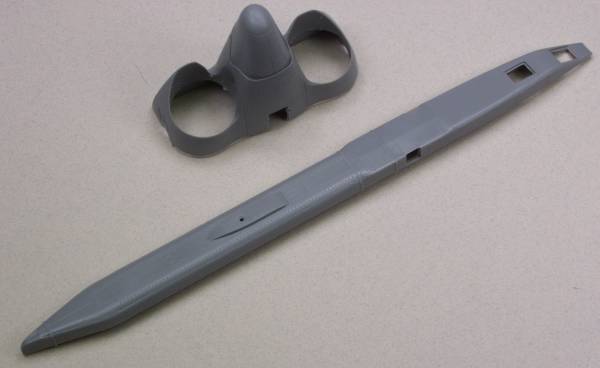
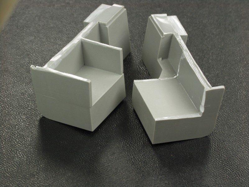
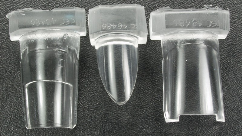
First lets deal with correction items. As I mentioned above there is some issues with the shape of the nose section from the inlets forward. The Cutting Edge set [CEC48486] provides corrected nose halves molded in light gray resin. It features recessed panel lines but no fastener detail. The parts are crisply molded with minimal flash and areas to be trimmed away. There are no pour stubs. I found no surface defects, pin holes or short shots. My major beef with these parts are that the panel lines are lighter and without the rather over done rivet detail that the rest of the fuselage exhibits. I think they will look too much like a graft. The set includes are new pitot tube for the nose cone. Other disadvantages include the nose cone, which on the kit can be posed open but would need to be cut off the new nose in order to that. Also the instructions warn that other after market cockpit sets designed for the kit may required modification to fit as the kit nose is too wide. The set comes with replacement clear parts as the kit parts won't fit. These are cast and while clear are a bit thicker than the kit parts and don't have as well defined frame lines and rivet detail as the kit parts. The set also addresses an issue with the shape of the top of the tail fin which in the kit is just wrong. The replacement part does have rivet detail but it's a bit finer than the kit so again it may make it standout more that the incorrect kit part. The Set comes in a sturdy cardboard box with bubble pack between layers. The gray parts are bagged separately from the clear and both are in zip lock bags. The instructions are on an 8 1/2 x 11" sheet printed on one side and while brief should be adequate. Another review of this set can be found here. See photos below.
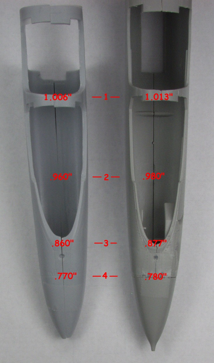
I initially wanted to build a Vigilante in the markings of the aircraft that discovered the Hanoi Hilton, for that I needed an early version. The Trumpeter kit is sort of a bastard in that it includes both early and late version features. One late version feature I needed to replace was the intakes. The early versions were shaped differently. Again Cutting Edge to the rescue. Set number [CEC 48487] includes the correctly shaped early version intakes along with a set of seamless intake trunks. There are molded in a light gray resin. The one piece intakes replace several kit parts and are beautifully detail. The parts are flash free. They do have sizable pour blocks but the cuts are straight so should not be that difficult. I found no surface defects, pin holes or short shots. The set comes in a zip lock bag and I guess installing them must be self explanatory as there were no instructions with mine. See photo below.
And now for the detail oriented details.
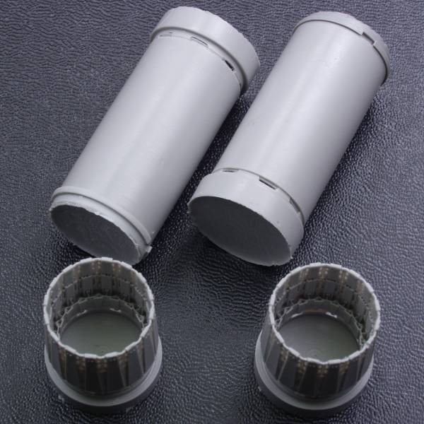
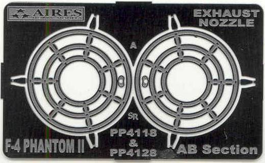
The first set in this category is the Aires [4118] Engine nozzle set. The kit parts pale in comparison to this set. It comes in a small cardboard box with the resin parts enclosed in a zip lock bag. The parts are molded in a gray resin and the level of detail in the tail feathers section is incredible. There was virtually no flash to be seen and no pin holes or short shots. Included with the set is a small photo etch fret with two fuel injection rings. The instructions are on a small sheet folded to fit the box. The set I have is labeled for the F-4 but they used the same engines as the Vigilante. Aires has since released a set labeled for the Vigilante. See the photos below.
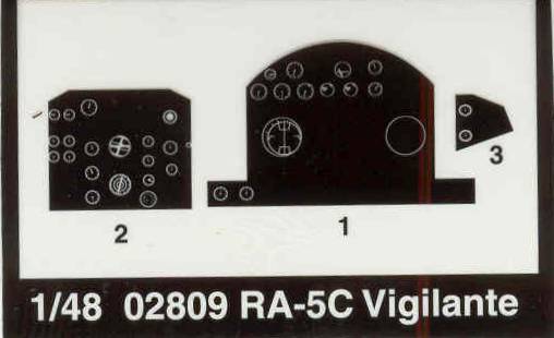
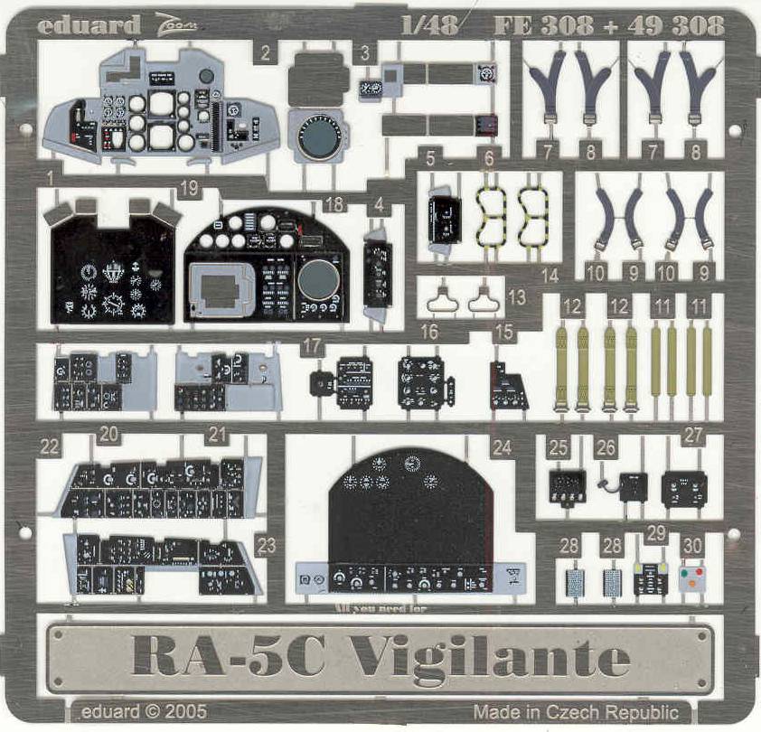
Next on the list is an Eduard Zoom set [49308] to dress up the cockpit. I could never paint it up to look as nice as the Eduard set. The Zoom sets aren't as complete as the full sets but there is more than enough to take the cockpit to the next level. See photo below.
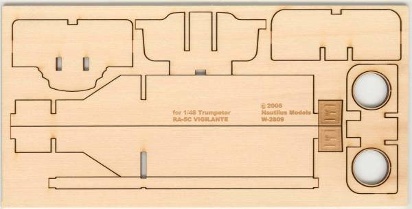
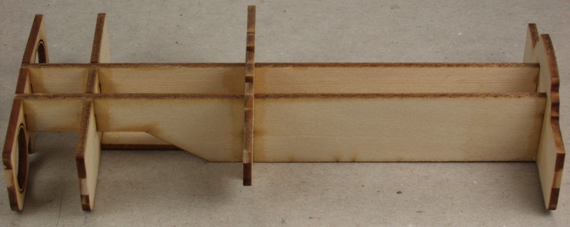
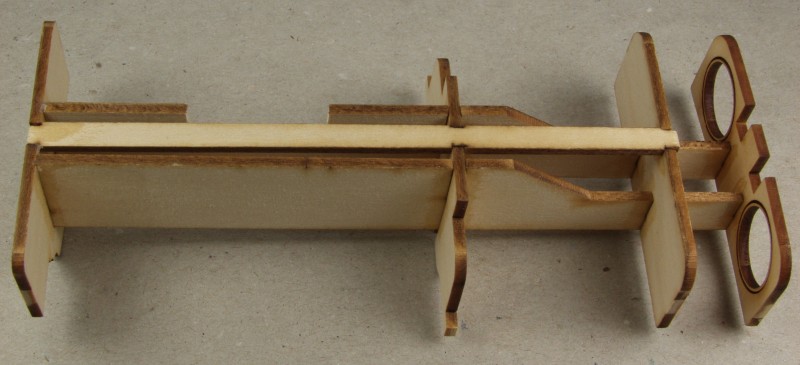
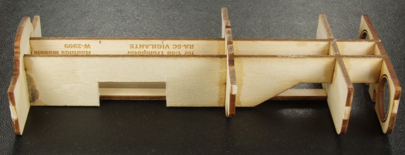
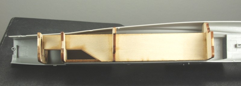
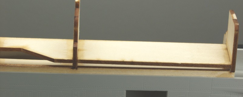
And lastly to address the problem with the lower fuselage during assembly the Nautilus [48-801] set which is made from 1/8" aircraft grade plywood and consists of four bulkheads that mount to a center spline and provide internal support to prevent the bottom fuselage seam from buckling inward. The parts are laser cut so they just break free from the sheet. The back bulkhead has holes that will accept the burner cans set above. It also has two intake plugs you can use. The only drawback to the set is that you can't use the kit engines but they can't be seen anyway. This can be purchased here. See photo below.


Links to kit build or reviews
A review can be found here and a build can be found here.
References
"A/RA-5 Vigilante Mini in Action" by Terry Love
RA-5C Vigilante Units in Combat, Osprey Combat Aircraft # 51 by Robert R. "Boom" Powell
"North American A-5A/RA-5C Vigilante" by Steve Ginter
Updated 11/19/16