
A-26B
A-26B
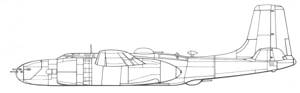
The A-26 was Douglas Aircraft's successor to the A-20 (DB-7) Havoc, also known as Douglas Boston, one of the most successful and widely operated types flown by Allied air forces in World War II. Designed by Ed Heinemann, Robert Donovan, and Ted R. Smith, the innovative NACA 65-215 laminar flow airfoil wing of the A-26 was the work of project aerodynamicist A.M.O. Smith.
The Douglas XA-26 prototype (AAC Ser. No. 41-19504) first flew on 10 July 1942 at Mines Field, El Segundo, with test pilot Benny Howard at the controls. Flight tests revealed excellent performance and handling, but engine cooling problems led to cowling changes and elimination of the propeller spinners on production aircraft. Repeated collapses during testing led to reinforcement of the nose landing gear.
The A-26 was originally built in two different configurations. The A-26B had a gun nose, which originally could be equipped with a combination of armament including .50 caliber machine guns, 20mm or 37mm auto cannon, or even a 75mm pack howitzer (which was never used operationally). Normally the gun nose version housed six (or later eight) .50 caliber machine guns, officially termed the "all-purpose nose", later commonly known as the "six-gun nose" or "eight-gun nose". The A-26C's "glass" nose, officially termed the "Bombardier nose", contained a Norden bombsight for medium altitude precision bombing. The A-26C nose section included two fixed M-2 guns, later replaced by underwing gun packs or internal guns in the wings.
After about 1,570 production aircraft, three guns were installed in each wing, coinciding with the introduction of the "eight-gun nose" for A-26Bs, giving some configurations as many as 14 .50 in machine guns in fixed forward mounts. An A-26C nose section could be replaced with an A-26B nose section, or vice versa, in a few man-hours, thus physically (and officially) changing the designation and operational role. The "flat-topped" canopy was changed in late 1944 after about 820 production aircraft, to a clam shell style with greatly improved visibility.
Alongside the pilot in an A-26B, a crew member typically served as navigator and gun loader for the pilot-operated nose guns. In an A-26C, that crew member served as navigator and bombardier, and relocated to the nose section for the bombing phase of an operation. A small number of A-26Cs were fitted with dual flight controls, some parts of which could be disabled in flight to allow limited access to the nose section. Access was through the lower section of the right-hand instrument panel, which was open to allow access to the nose for the bombardier, who would normally sit next to the pilot. This was similar to British designs like the Lancaster, Blenheim/Beaufort, Wellington, etc. A tractor-style "jump seat" was located behind the "navigator's seat." In most missions, a third crew member in the rear gunner's compartment operated the remotely controlled dorsal and ventral gun turrets, with access to and from the cockpit possible via the bomb bay only when that was empty. The gunner operated both dorsal and ventral turrets via a novel and complex (and problematic) dual-ended periscope sight, which was a vertical column running through the center of the rear compartment, with traversing and elevating/depressing periscope sights on each end. The gunner sat on a seat facing rearward, and looked into a binocular periscope sight mounted on the column, controlling the guns with a pair of handles on either side of the column. When aiming above the center line of the aircraft, the mirror in the center of the column would flip, showing the gunner what the upper periscope was seeing. When he pressed the handles downward, as the bead passed the center line the mirror would automatically flip, transferring the sight "seamlessly" to the lower periscope. The guns would aim wherever the periscope was aimed, automatically transferring between upper and lower turrets as required, and computing for parallax and other factors. While novel and theoretically effective, a great deal of time and trouble was spent trying to get the system to work effectively, which delayed production, and it was difficult to keep maintained in the field even once production startedThe Kit
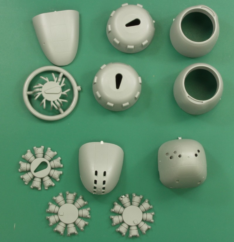
The
clear
parts are nicely thin and clear, a bit of distortion can be seen
in the curved portions. Also included are a window, a couple
inspection windows, landing light lenses, navigation light
lenses. The opening portion of the canopy used on this version
is a separate piece should you want to display it open.
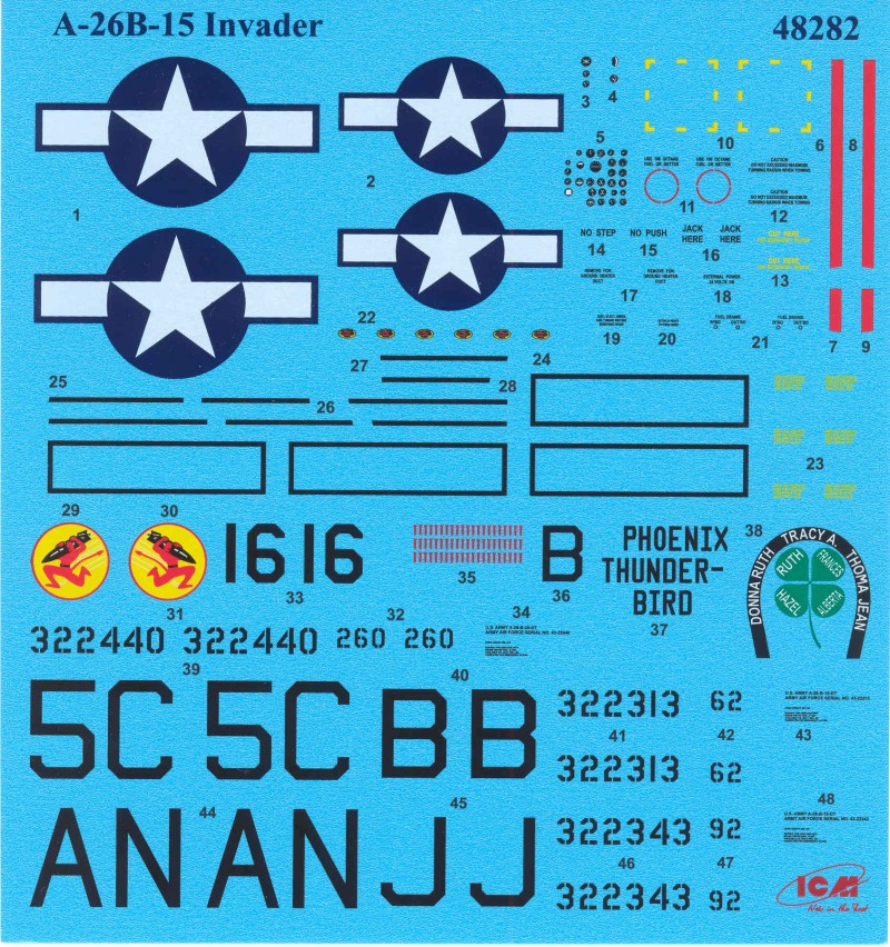
The
decals have a glossy finish and are in register. I'm not sure
some of the light colored markings are opaque enough, difficult
to tell on the sheet. Most of the small printing is readable
under magnification. The sheet provides marking for three
aircraft, the first is from the 671st BS/416th BG at A55 Melun,
France, early 1945. The second is from the 553rd BS386 BG A92
St. Trond, Belgium, April 1945. And the third 84th BS/47th BG,
Grosseta Italy, early 1945. ICM decals seem to be of variable
quality, I have used some that fine and others not so much.
The
instructions are an A4 sized 24 page booklet in
the portrait format and stapled at the spine. The
cover pages are printed on glossy stock while the
balance is printed on plain paper. The first page
has a brief history and specifications printed in
Russian and English, a color chart with Revell and
Tamiya numbers and generic names in Russian and
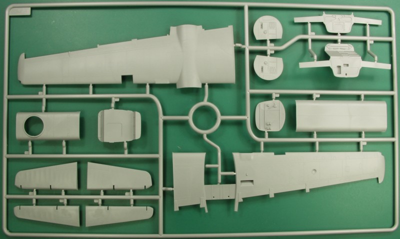
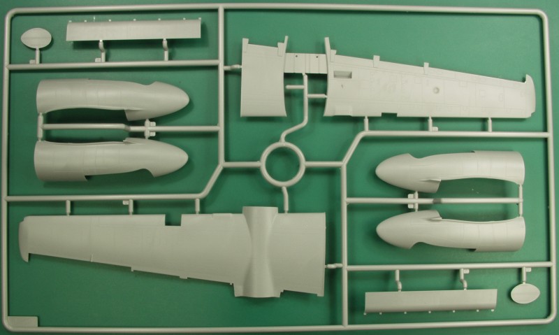
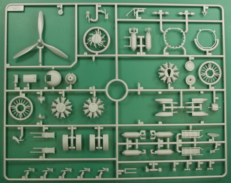
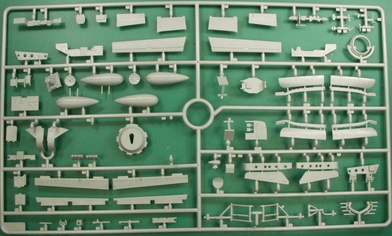
English and an icon chart. Pages two through four
are parts maps, parts that are not to be used are
shaded in color. Assembly diagrams start on page
five and continue through page twenty-one. Page
twenty-two has a gray scale isometric drawing of
the completed kit and pages twenty-three and
twenty-four have the painting and marking diagrams
for the three options on the decal sheet. The
assembly diagrams are all clear and easy to follow
with color call outs.
After
Market
Goodies
This
series of kits from ICM will most likely be very
popular and I expect we will see a lot of after
market from all the usual suspects. If I acquire
any of it I will post it here.
Conclusions
ICM
has really stepped up their game over the past
couple of years and their kits have gone from
being more like limited run kits to more like main
stream. With the possible exception Tamiya this
kit is equal to the likes of the newer Airfix and
Revell kits. This one is simple enough assembly
wise that even newbies should be able to build a
presentable model from it. Highly recommended.
Links
to kit build or reviews
An
inbox and partial build review can be found here
and another in box here
that includes some nice period photos
References
A-26
Invader in Action by Jim Mesko
A-26
Invader Units of World War 2 by Jim Roeder