
B-57B Canberra
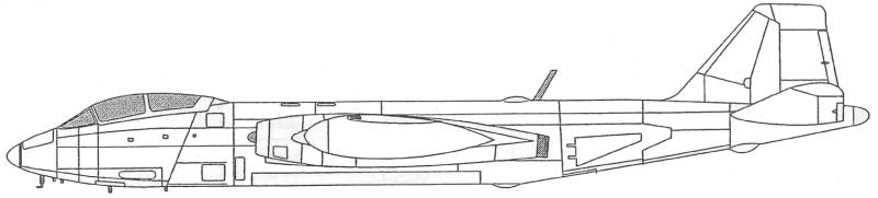
The B-57B
At the outbreak of the Korean War in 1950, the United States Air Force found itself in dire need of an all-weather interdiction aircraft. The piston-engine Douglas A-26 Invaders were limited to daytime and fair weather operations and were in short supply. Thus, on September 16, 1950 the USAF issued a request for a jet-powered bomber with a top speed of 630 mph (1,020 km/h), ceiling of 40,000 feet (12,190 m), and range of 1,150 miles (1,850 km). Full all-weather capability and secondary reconnaissance role had to be included in the design. To expedite the process, only projects based on existing aircraft were considered. The contenders included the Martin XB-51, and the North American B-45 Tornado and AJ Savage. In an extremely rare move, foreign aircraft including the Canadian Avro Canada CF-100 Canuck and the British English Electric Canberra were also given consideration. The AJ and B-45 were quickly dismissed because their outdated designs had limited growth potential. The all-weather interceptor CF-100 was too small and lacked sufficient range. The XB-51, while very promising and much faster, had limited maneuverability, a small weapons bay, and limited range and endurance.
On February 21, 1951, a British Canberra B.2 (flown by Roland Beamont) became the first-ever jet to make a non-stop unrefueled flight across the Atlantic Ocean, arriving in the United States for USAF evaluation. The Canberra emerged a clear winner of February 26 fly off against the XB-51. Since English Electric was unable to produce enough aircraft for both the RAF and the USAF, on April 3, 1951 Martin was granted the license to build Canberras, designated B-57 (Martin Model 272) in the US. To expedite production, the first B-57A's were largely identical to the Canberra B.2s with the exception of more powerful Armstrong Siddeley Sapphire engines of 7,200 lbf (32 kN) of thrust, also license-built in the US as Wright J65s. In addition, canopy and fuselage windows were slightly revised, the crew was reduced from three to two, wingtip fuel tanks were added, engine nacelles were modified with additional cooling scoops, and the conventional "clamshell" bomb-bay doors were replaced with a low-drag rotating door originally designed for the XB-51.
The first production aircraft flew on July 20, 1953, and was accepted by USAF on August 20. During the production run from 1953 to 1957, a total of 403 B-57s were built.
The B-57A was not considered combat-ready by the USAF and the aircraft were used solely for testing and development. One of the aircraft was given to the National Oceanic and Atmospheric Administration (NOAA) which fitted it with a new nose radome and used it to track hurricanes. The reason for such limited production was that the distinctly British B-57A was considered unfit for USAF service. Particularly contentious were the odd cockpit arrangement and the lack of guns, the British Canberra having been designed as a high-speed, high altitude bomber rather than for close air support. The definitive B-57B introduced a new tandem cockpit with a bubble canopy, the engines were now started with a pyrotechnic cartridge, the air brakes were moved from the wings to the sides of the fuselage for increased effectiveness, the controls were now boosted, four hard points were fitted under the wings, and the aircraft was given gun armament in the form of 8 x 0.50 in (12.7 mm) Browning machine guns in the wings, later replaced by 4 x 20 mm M39 cannons. The first B-57B flew on June 18, 1954. The aircraft initially suffered from the same engine malfunctions as the RB-57As and several were lost in high-speed low-level operations due to a faulty tail plane actuator which caused the aircraft to dive into the ground. The USAF considered the B-57B inadequate for the night intruder role and Martin put all aircraft through an extensive avionics upgrade. Regardless, by the end of 1957 the USAF tactical squadrons were being re-equipped with supersonic F-100 Super Sabers. The complete retirement was delayed, however, by the start of the Vietnam War.
The B-57 went on to serve with distinction through nine years of combat for the most part filling the role of tactical bomber but was modified and up graded to perform a wide variety of other tasks as well. Following the war they were reassigned to peacetime missions and the last flying example was used by NASA for high altitude evaluation missions. It had served for 29 years as a U.S. military aircraft.
The Kit
The
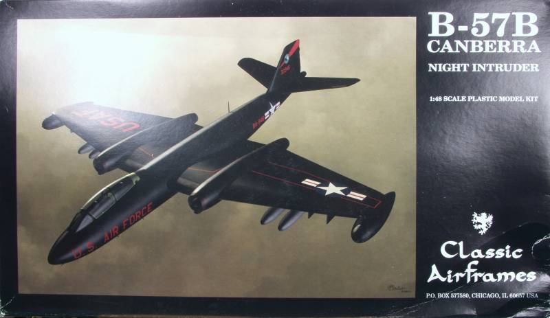
Classic Airframes B-57B comes in a typical CA top
open two part box
with an attractive rendition of the B-57 on the
top. In side the box
was a large zip lock bag and two smaller zip lock
bags. The larger
contained the injection molded parts and the two
smaller had resin
parts in one and the clear parts in another.
(Note: Mine came from eBay
and this may have not been the way it came from
the factory) Due to the
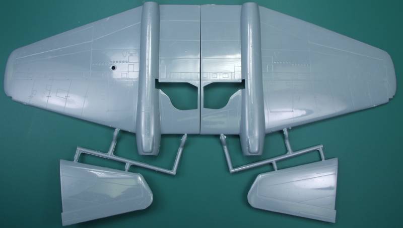
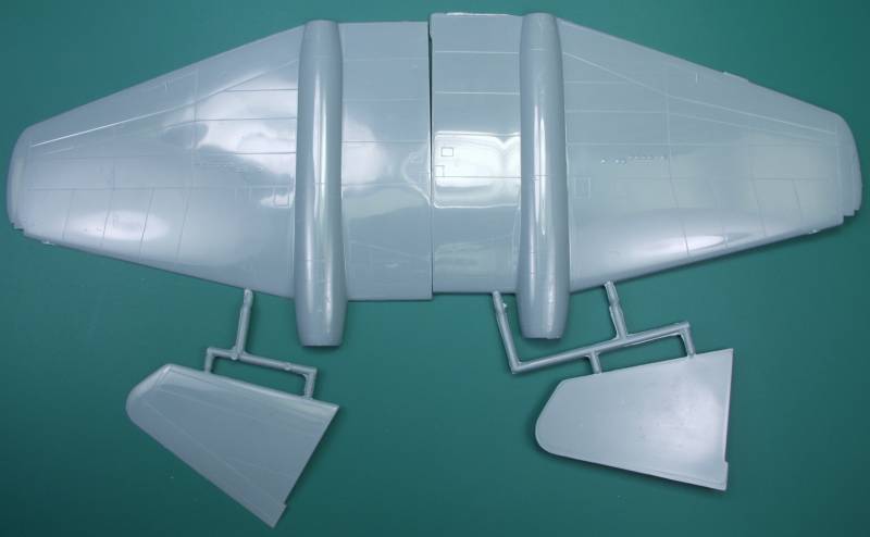
large size of some of the parts the fuselage
halves were not on a sprue
and the wings had the tail surfaces attached by
small sprues to them.
The injection molded
parts are a blue gray in color and feature
recessed panel lines that are fine and uniform for
the most part
although I did find a couple that faded out to
nothing and raised
detail where appropriate. The surface has a glossy
finish and was for
the most part defect free. I did find a couple
small globs that will
need to be sanded down and there was quite a bit
of abrasion marks from
shipping that may need to be buffed out depending
on what kind of
finish you want. All of the parts exhibited a bit
of flash but not
nearly as bad as many limited run kits. The sprue
gates are heavy on
many parts so care will be required when removing
parts from sprues.
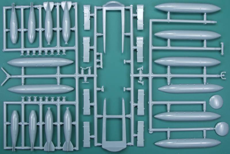
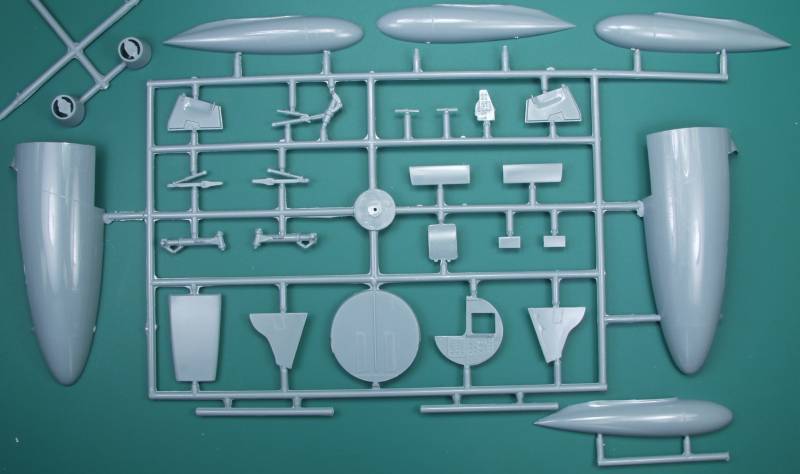
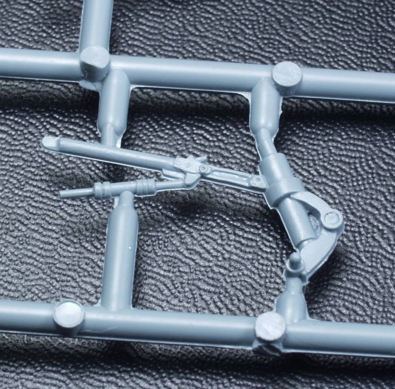
The fuselage is molded in four parts to accommodate different versions and this usually creates fit issues so care will be needed there as well. There are no ejector pin towers or marks that will show when complete but a couple will need to be removed to facilitate installing the cockpit and assembling the wings and tail planes. There are round stubby wing spars provided to strengthen the wing to fuselage join, the tail planes are a butt joint. Because of the size of the wings I might consider using some longer stubs and some pins on the tail plane as well. The kit comes with under wing bombs and napalm canisters. The fuse spinners on the bombs are a little heavy handed. As with most short run kits there are no alignment pins. Altogether there are 94 parts molded in gray. Note that there are 5 parts that are 'X'ed out as being used on other versions. See below.
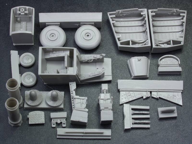
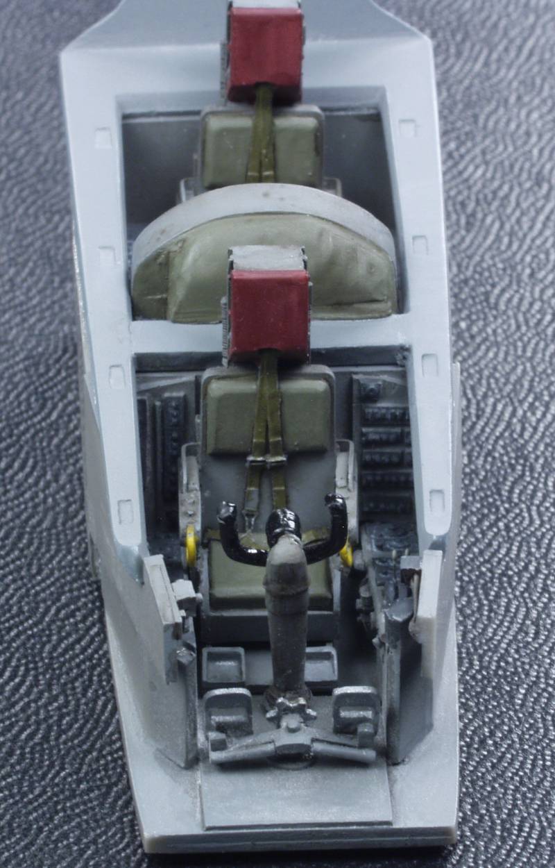
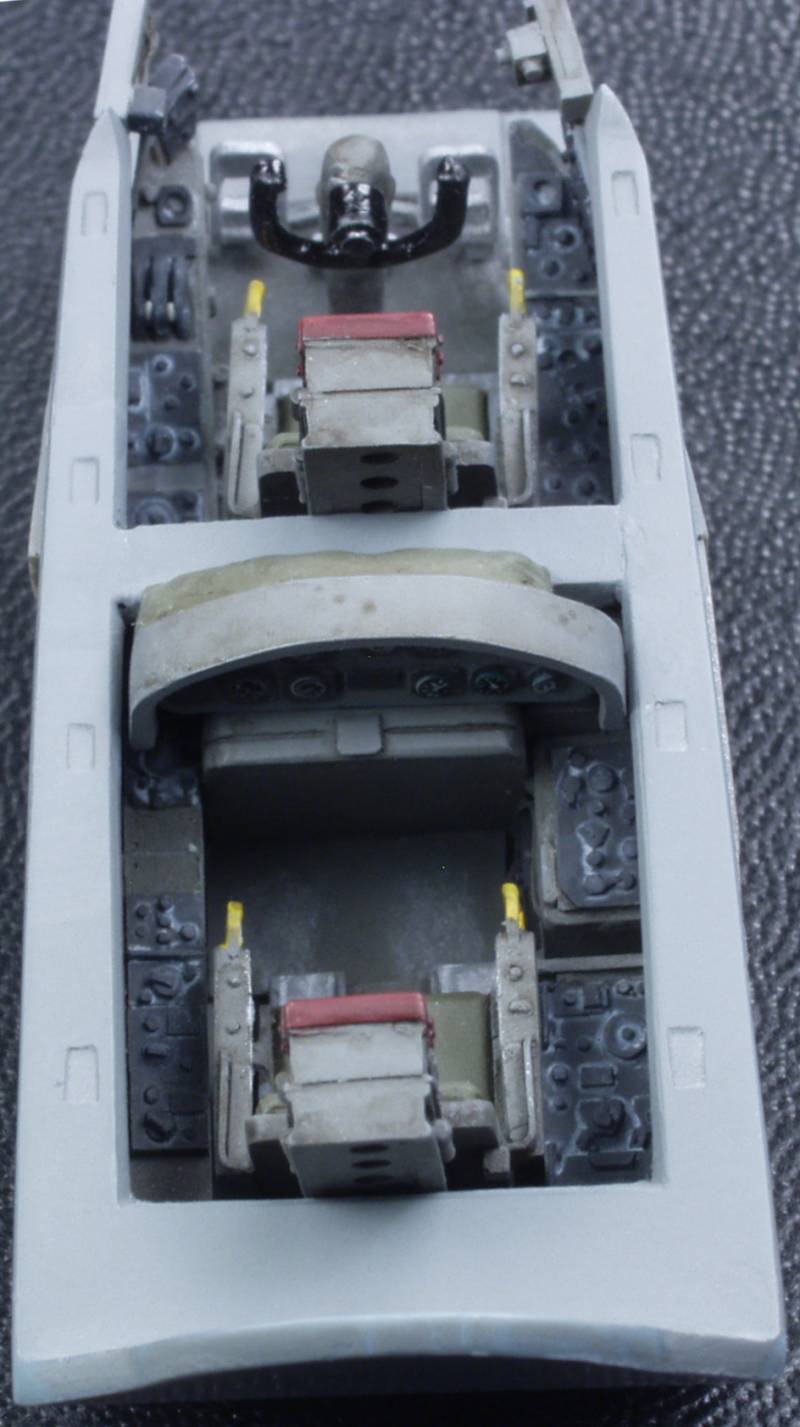
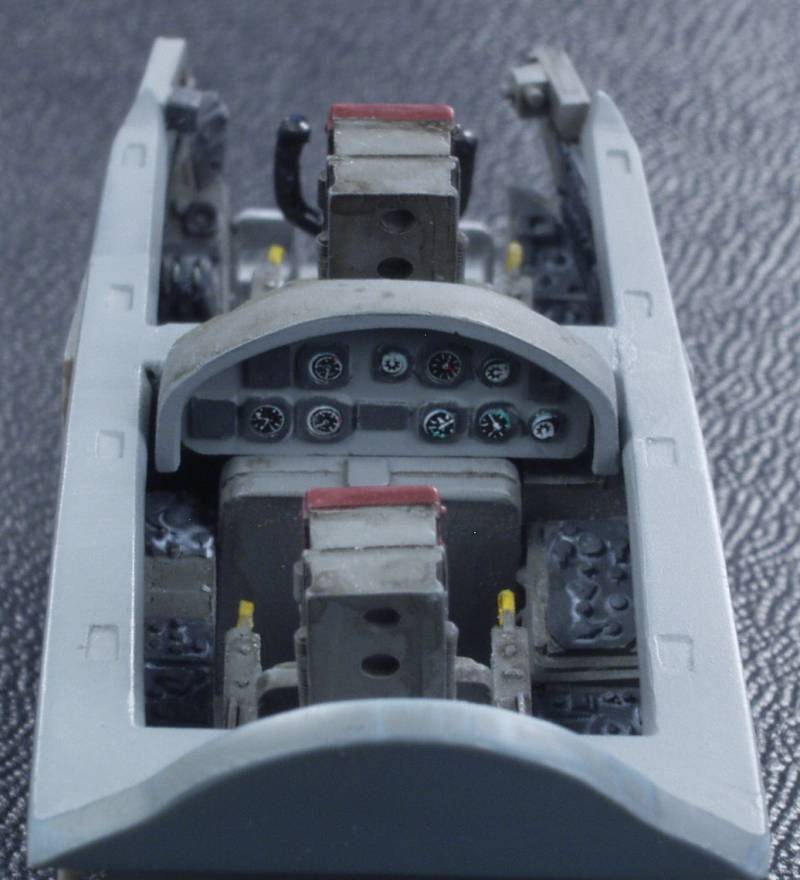
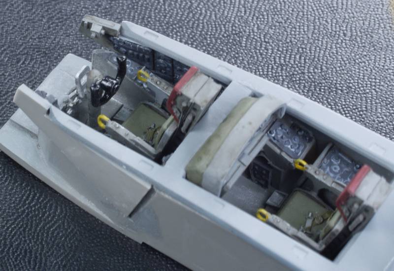
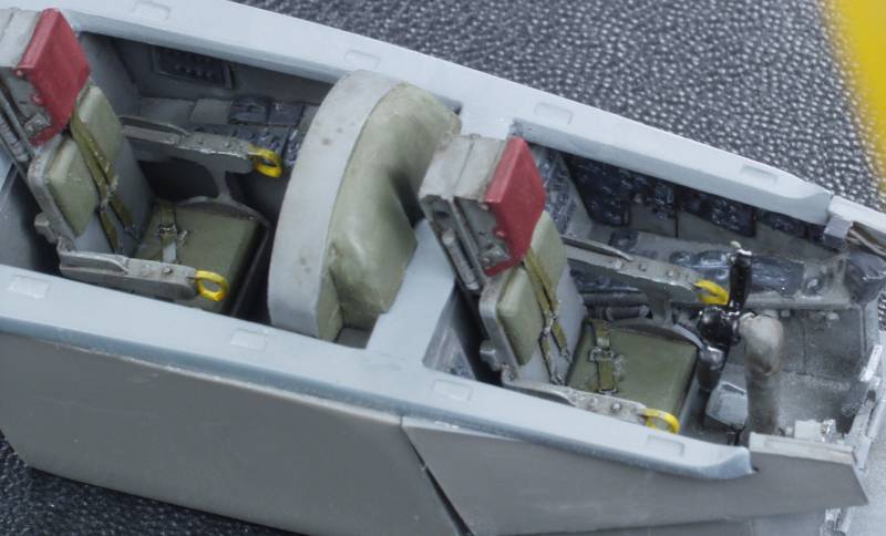
The resin parts are molded in a gray resin and consist of the following; two very nicely done main gear bays with structural and other details molded in, the cockpit tub with side consoles with a good deal of raised detail, two very nice ejection seats with harnesses molded in, main wheels and nose wheels (not weighted), engine fronts and seamless tail pipes with back engine detail, nose gear bay with molded in detail, instrument and side panels for both positions, rudder pedals, instrument panel combing, canopy brace if canopy is displayed open, an antenna and a couple pieces that aren't shown in the instructions. The parts are all crisply molded with no pin holes or short shots to be found. Altogether there are 24 resin parts, see below.
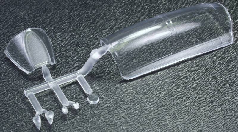
The clear parts are nice and clear, a little on the heavy side but they have nicely raised frame areas for easy masking and should look great with a coat of Future. Wing tip lights and a camera view port are included for a total of 7 parts, see below.
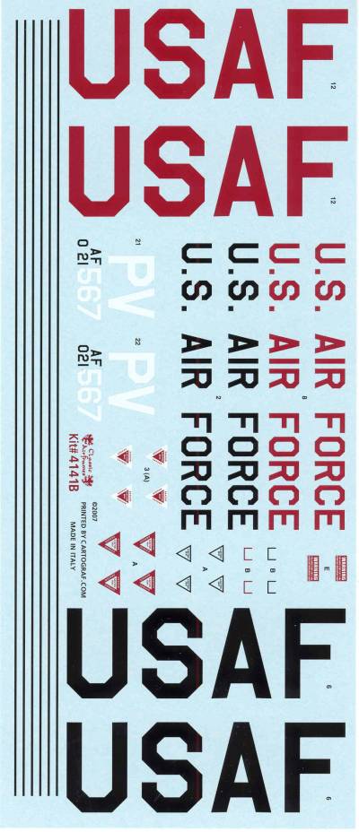
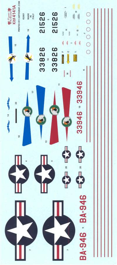
The decals are on two large sheets printed by Cartograph. They are thin with minimal clear areas and opaque and well registered. They contain markings for four aircraft and a good selection of stencils. See below.
The instructions are printed on an A4 sized sheet folded in half with a half sheet insert creating six pages. The first page has history and specifications and the usual warning that this kit is for experienced modelers. Page two has an icon chart, a list of colors required by name only and parts map. Page three through six are assembly instructions. There is one A4 sheet with painting and marking diagrams for the four aircraft on the decal sheet and an additional half sheet printed on one side with stencil information.
After Market Goodies
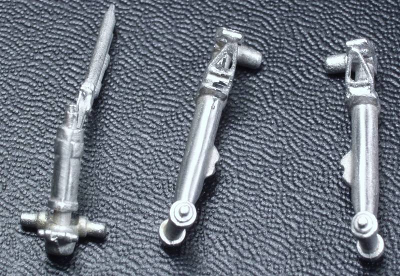
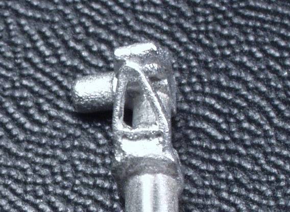
SAC (Scale Aircraft Conversions) makes a replacement landing gear set (48011) in cast metal that includes a cast metal nose gear bay and a shortened nose gear as well as new main gear parts, The detail on the cast gear bay is not as sharp as the supplied resin but not bad and it reduces the amount of weight you need to add to the nose to keep it setting on the nose gear. The metal parts are much easier to clean up than the kit parts which display a good bit of mold alignment issues. The kit nose gear must be modified right out of the box and it is still too long. The torque links on the kit main gear look horrible while the SAC set was sharp enough to be drilled out for a nice appearance.
Here is an example of what the kit gear looks like followed by a couple of photos of the SAC set after being cleaned up.
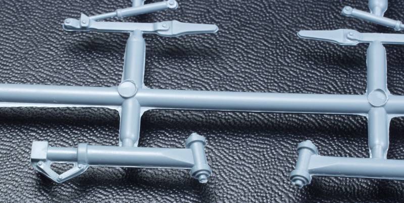
While I'm not a real big fan of these aftermarket cast metal gear sets I can highly recommend this one. A review and photo of the set parts can be found here.
Conclusions
This is another nice kit from Classic Airframes that as usual for short run kits will require more clean up and fitting time than assembly time but in the end you will be rewarded with a very nicely detail kit of the B-57. Reviews don't indicate any problems beyond the ordinary expected with this type of kit. Recommended for modelers with some short run multimedia kit experience.
Links to kit build or reviews
Build / reviews can be found here and here.
References
Martin B-57 Canberra, The Complete Record by Robert C. Mikesh
The Build
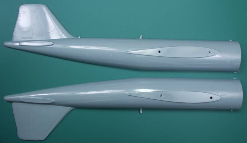
I started on this by first cleaning up all of the Resin parts, removing them from their pour blocks and sanding away any excess resin. The main gear bay needed to have the top sanded down until the material was almost translucent to guarantee that it wouldn't effect the fit of the wing halves. The cockpit can be added after the fuselage was assembled so I proceeded with that. While the instructions give you the option of gluing the forward and rear portions of the fuselage together before or after they are glued together I recommend you do them before as you can better control the alignment and glue from the inside of the joint. The joint is on a panel line so I filed a slight chamfer on each edge of the joint so even if I got some glue squeeze out I'd still have a good guide for rescribing the joint.
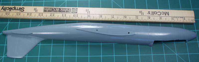
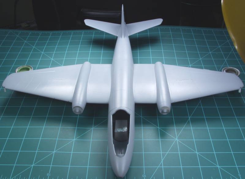
A photo next to a yard stick gives you an idea of the fuselage length.
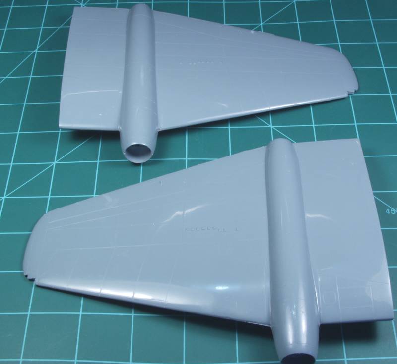
The wings were glued together as were the tail surfaces. Things fit reasonably well but the trailing edges were rather thick so some time was spent sanding them down a bit.
Only real bad fit was on one wing next to the engine, nothing a little filler and sanding wouldn't fix.
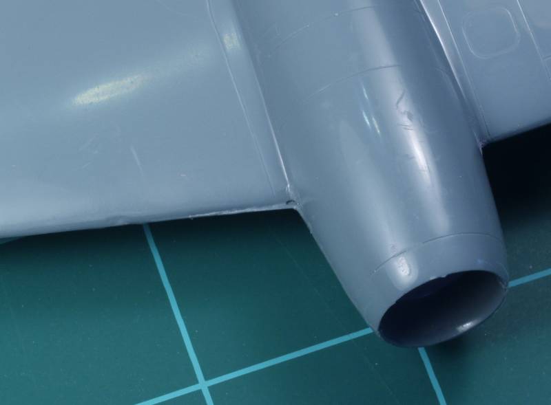
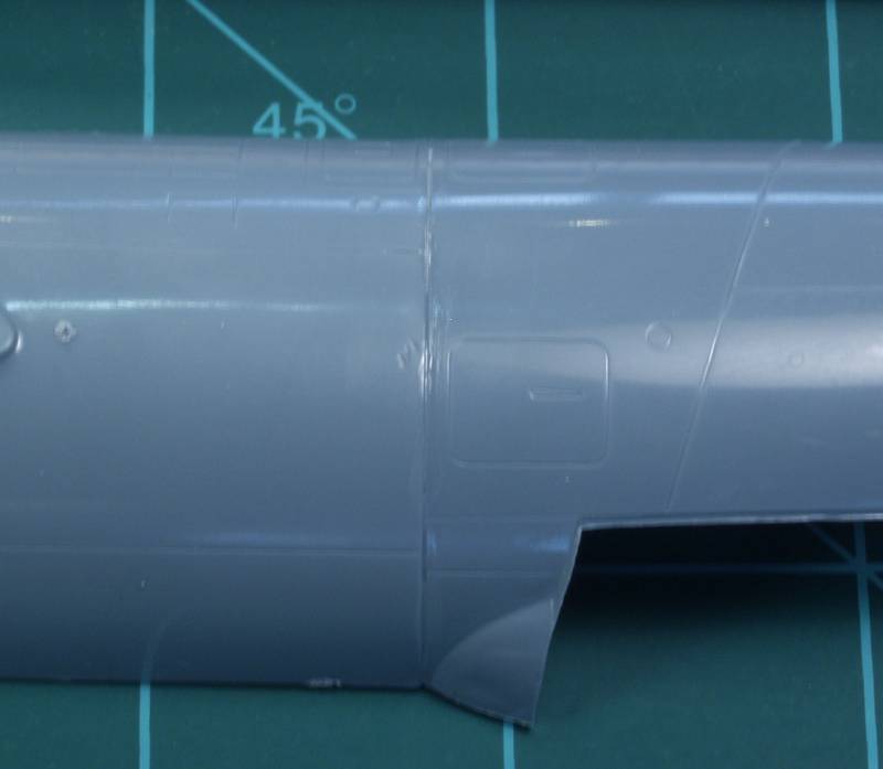
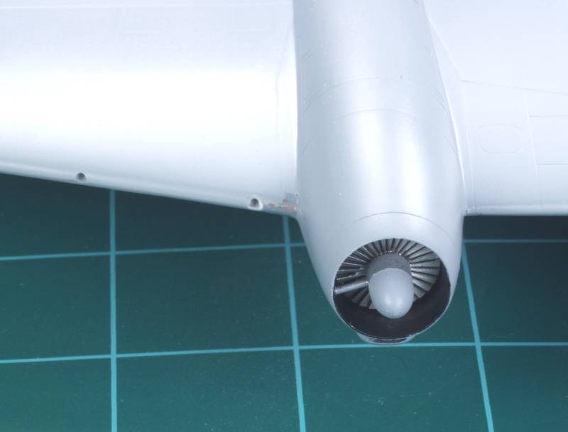
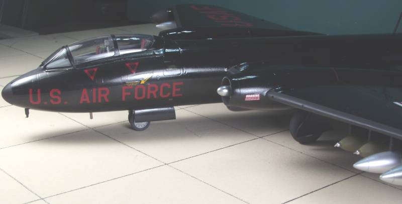
The air intake below the engine should be open but it was molded closed so I opened it up using drills and an x-acto knife. It was solid plastic and I couldn't go all the way through so I went as deep as I could. It looks a little crude but once painted flat black inside it, any roughness won't be all that visible.
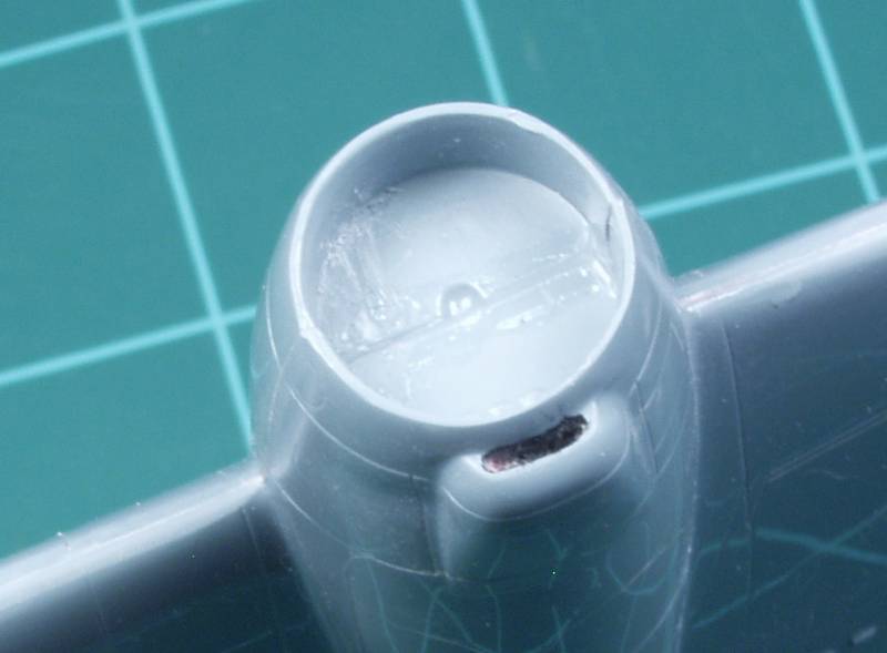
There was only a faint indication on the wings where the 20mm cannons were located so I drilled them out and installed some styrene tube to serve and blast tubes. No gun barrels can be seen in any of the photos I have so I assume they are recessed. I should have also opened up the shell ejector chute opening on the bottom of the wings but forgot to until it was too late. I also added the exhaust vent for the black powder starter that runs from the engine nose cone to the outside of the cowl.
The fuselage was assembled, wings and tail attached and the nose gear bay installed. I needed to get to this stage to determine haw much weight would be needed in the nose. Fit was OK but some filler was required at both the wing and tail joints. Once this was taken care of a coat of primer was put on.
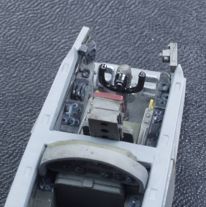
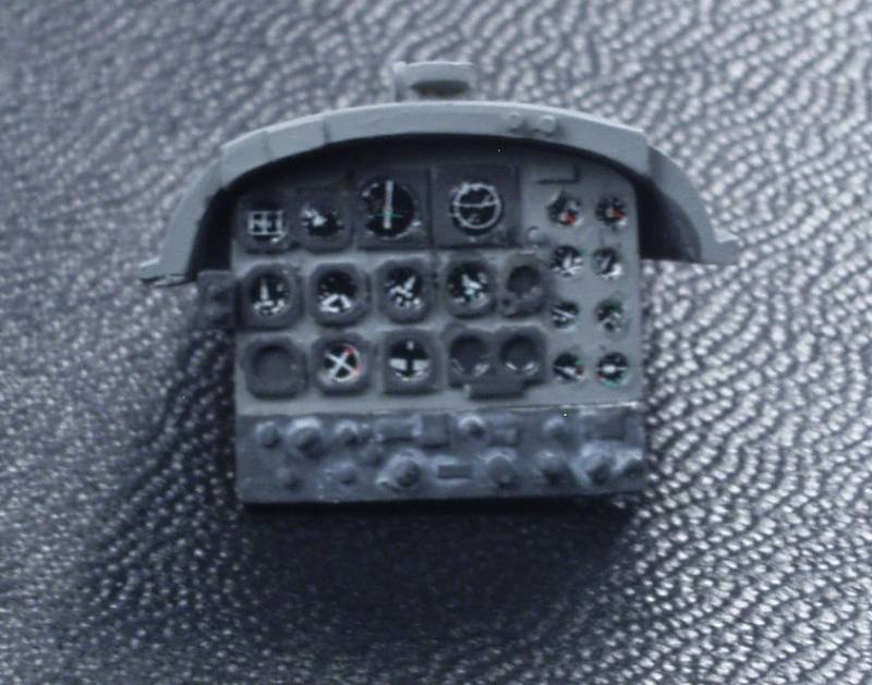
Next up the cockpit parts were painted and assembled. The kit supplies nice looking ejection seats and other details. Unfortunately cockpits from the 50's are a little colorless being mostly black panels with black knobs. I highlighted the panels with some gray wash to pop the detail a bit. Airscale decals were used on the instrument panels and a couple PE throttle levers were added from the spares box. Unfortunately I didn't realize until after the fact that my only photo of the main panel was blurred but I put it here anyway.
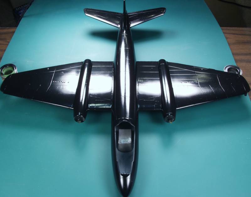
The kit was then given a coat of gloss black. This is Krylon that has been decanted and is the old formula. I found that this glossy black finish was as unforgiving as a bare metal finish and was a finger print and dust magnet.
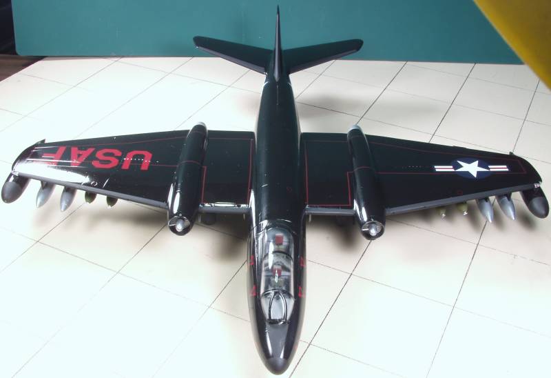
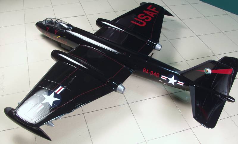
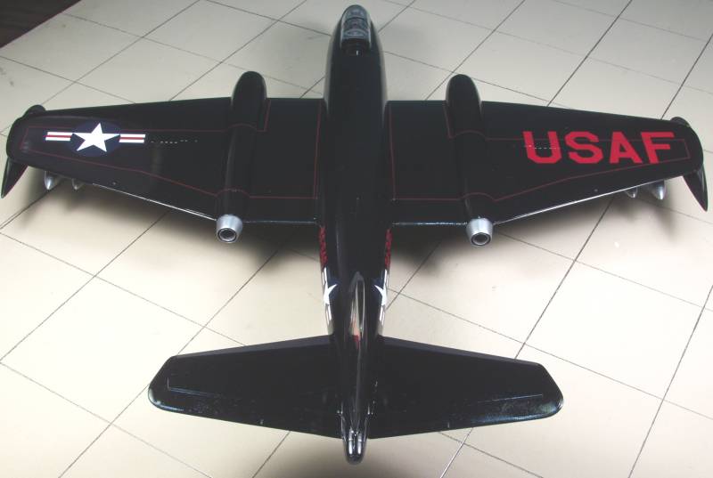
At this point I started applying decals. The kit decals went on very well and settled down with a little Microsol. The only issue I had was that the decals seemed to take a long time to loosen from the backing, warmer water may have helped. They were durable enough to allow positioning them with out them breaking up. I think the USAF decal was the largest decal I have every applied.
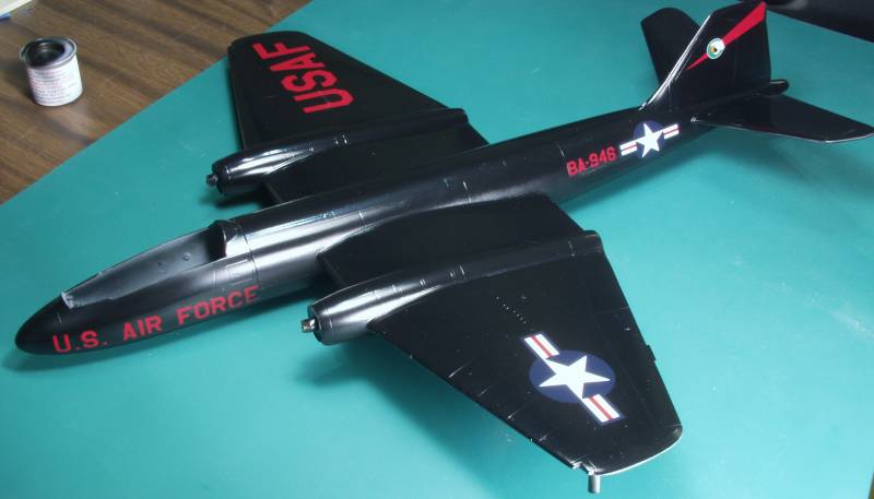
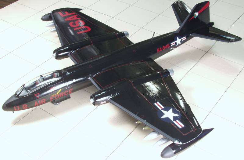
Once all the decals had been installed all the cockpit and canopy was installed and all the rest of the detail parts were added. The canopy fit was problematic and I'm still not real happy with it. The kit bombs were not very well done so I replaced them with some Hasegawa bombs from one of their armament sets. The wing tip tanks had no positive locators and were fiddly to locate so I used 5 minute epoxy on them. The flat black on the leading edges of the wings tail, nose and tip tanks is a rubberized coating that was designed to prevent paint chipping and peeling.
Not only was the gloss finish difficult to work with it also made photography hard. I guess I need some light diffusers.
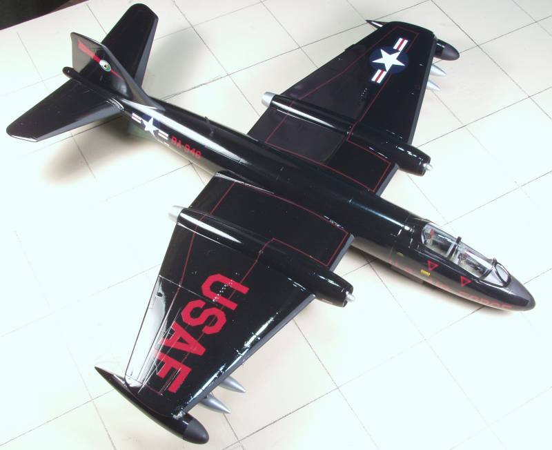
The kit was a typical Classic Airframes build, a lot of test fitting and trimming but wasn't all that bad. If I had to do it over again I might have gone for the SEA camouflage instead of black, but I still think it's a cool scheme.