
Martin Baltimore
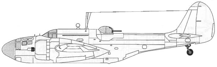
The Martin Baltimore was a further development of the Martin Maryland. While keeping the same design layout, the Baltimore was heavier, roomier and was powered by larger engines than the Maryland. The first of these was flown in June of 1941 and deliveries of 50 Baltimore I's and 100 Baltimore II's began soon after with the first reaching Britain in October of 1941. Early models featured an armament of eleven 30 caliber Browning machine guns, four in the wings, two in the rear dorsal position (an open position in early models and a turret later), one in the ventral hatch and four mounted in the belly mounted at an angle to the rear as "scare" guns. The Mark I's were retained for use in training squadrons while the Mark II's went to squadrons.
The bulk of the first order was made up of Mark III's which featured a Boulton Paul hydraulically operated dorsal turret fitted with four 303 Brownings of British manufacture. The Lend-Lease aircraft, which had to be initially ordered by the U.S. Army Air Corps, were given the designation A-30, though all were delivered to the RAF. The first of these was the Mark IIIA which differed from the Mark III in featuring an electrically operated Martin dorsal turret of reduced profile containing a pair of 50 caliber Brownings. 281 of these were delivered followed by 294 A-30A's or Mark VI's which were similar to the IIIA. The entire final order of 600, known to the Army Air Corps as A-30A's but to the RAF as Mark V's featured 50 caliber wing guns and more powerful Wright R-2600-29 engines. The first of these appeared in December of 1942 and when production ended in May of 1944, 1,575 Baltimores had been built. Most of these were delivered directly to the Middle East. Pilots generally liked the Baltimore, the main complaint being that its narrow fuselage prevented crew members from being able to move around during flight and more drastically made it almost impossible for another crew member from taking over the controls should the pilot be wounded. This was also the same problem that was found with the Douglas Boston / Havoc series.
The Kit
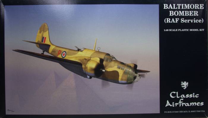
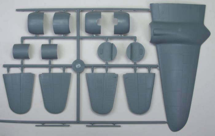
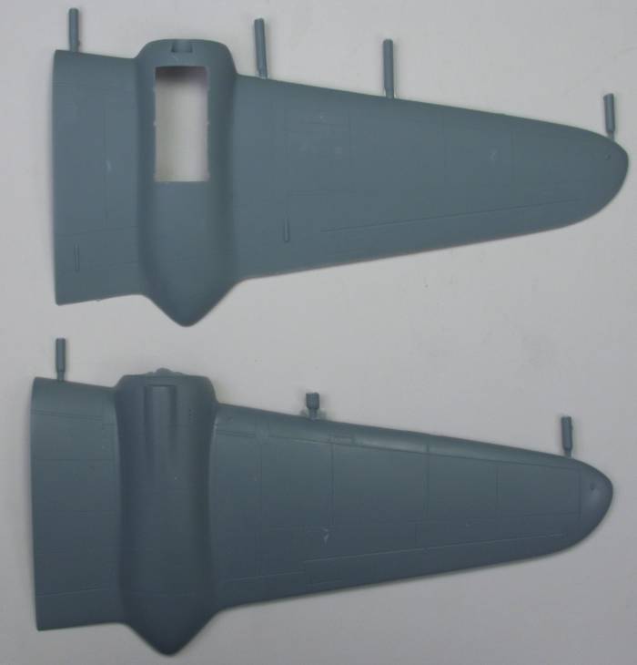
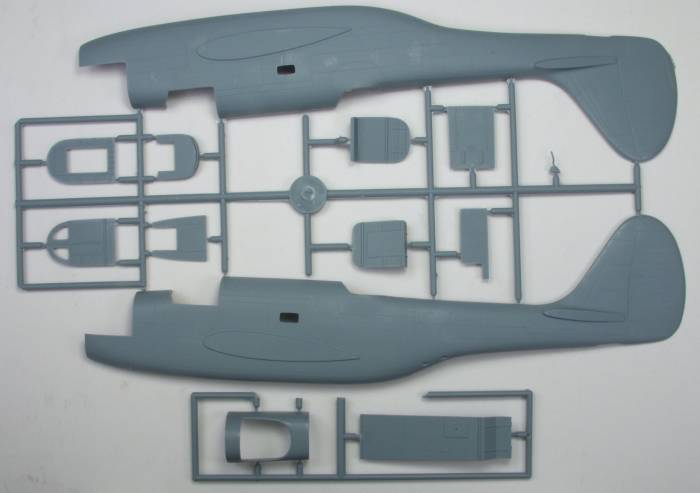
The Classic Airframes kit comes in a two part top open box typical of Classic Airframes with nice artwork of a Baltimore flying over the pyramids. Inside the box there is a large zip lock bag containing all but the clear parts and a smaller bag with those. Inside the large bag is a smaller bag containing the resin parts. The parts are molded in what has become typical for CA a blue gray plastic. The parts feature recessed panel lines that are fine and uniform. The parts have a semi gloss to flat finish and there is some light flash on some of the parts. The control surfaces are all fixed and feature very nicely rendered fabric detail. Looking over the air frame parts I found no sink holes or other surface blemishes. The kit can be made up as either an early model with an open gun position or the later version with the Martin turret. The "scare" gun locations are recessed into the rear fuselage and these would need to be filled if building the later version. While the turret is nicely rendered with resin parts only the guns are provided for the open position which could use some additional detail. The main gear bays are boxed in with a rather unusual piece that gets folded and dose have some nice detail molded into it. The gear doors also feature recessed rivet detail which is a nice change from ejector pin marks found on many kits. The only ejector marks that will need to be addressed are some towers on the inside of the fuselage. The props are the "build them yourself" style which feature plastic blades and nice resin hubs. The interior is very nicely done with a combination of plastic and resin parts and even includes the radio operators position which will all but disappear when the fuselage is closed. I would strongly suggest replacing the tail wheel strut with a piece of brass or other suitable wire as the supplied part is very delicate looking. It can be seen in the forth photo down between the two fuselage tail sections. Altogether there are 71 parts molded in gray. See photos below.
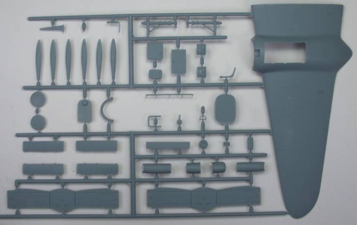
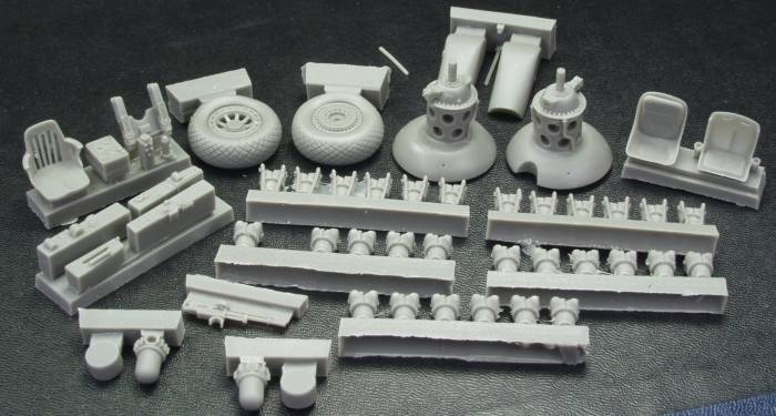
The resin parts supplied include both engines with separate cylinders, propeller hubs crew seats, guns, cockpit side consoles, engine air intakes, wheels, oil cooler inserts and instrument panel. The instrument panel has some nice raised detail but no film or raised parts for the instruments, just recesses which could use some instrument decals in them. All these parts are molded in a dark gray resin and were free of any bubbles or short shots. A couple pieces had some light flash but it should clean up easily. altogether there are 53 resin parts. See photo below.
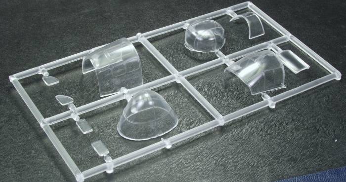
The clear parts are thin and relative clear and should look great after a coat of future. The frame lines are raised which should help in masking. There are a total of 10 clear parts for a kit total of 134 parts. See photo below.
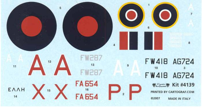
The decals are very nice looking, thin, glossy, in register and the red looks correct for British markings. The sheet provides markings for four aircraft, one early and three late model. Two are in typical British desert colors, one all black and one in RAF Coastal command colors. See photo below.
The instructions are printed on two 8 1/2" x 14" size sheets printed on both sides and folded to create 8 pages. The first page has a brief history and specifications, the second page has an icon chart, paint color key giving paint names only, and a parts map. The remaining pages cover assembly. There is a separate sheet 8 1/2" x 11" that has the marking and camouflage information. It should be noted that the engine assembly instructions are in error. It has you assembling the back row of cylinders with the connecting rods facing the front of the engine which is wrong, they should face towards the rear.
Conclusions
This looks to be a really nice kit of a much overlooked aircraft. Like all Classic Airframes kits one must take the time to clean up and test fit parts before assembly but most reports indicate there are not major fit problems to deal with. That was easy to say but not the case in my situation anyway. I suggest reading my build log. I would recommend the kit to only experienced modelers with a lot of limited run kit experience.
Links to kit build or reviews
A build / review can be found here and an in box review here.
References
Profile Publications # 232 Martin Maryland and Baltimore Variants by Christopher F. Shores
Back to the MISC BRITISH page
The Build
As
with most aircraft the logical
place to start is the cockpit and interior as this needs to be done
before the fuselage can be assembled. This kit is no different. As I
had been forewarned that the various bulkheads were all over sized I
decided to address them before adding any of the small detail parts,
so
diverging from the instructions I assembled all the floors and
bulkheads into one assembly, let it thoroughly set up then sanded
every
thing to fit. I found that most of the bulkheads had a taper on the
edges to facilitate easy removal from the molds and I found that in
most cases sanding the edge till it was flat provide the relief
necessary to fit the fuselage. Once I was satisfied with the fit in
the
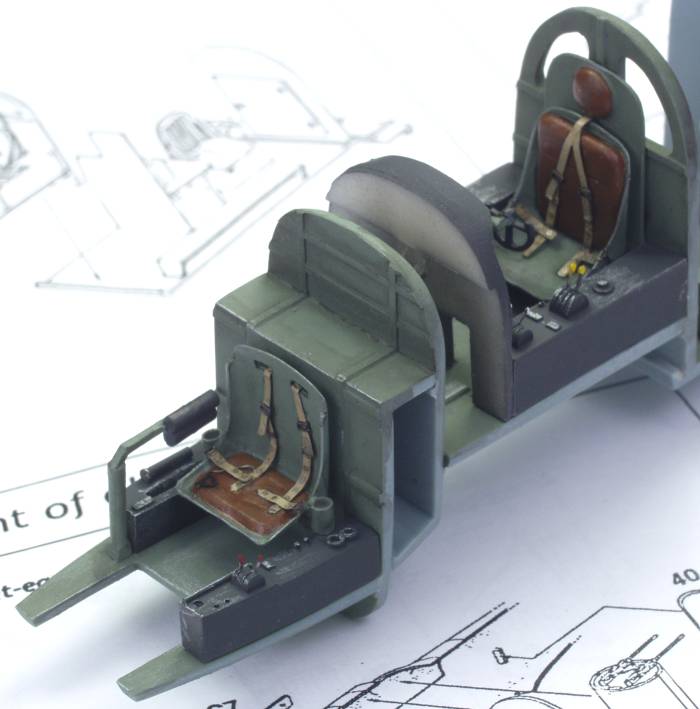
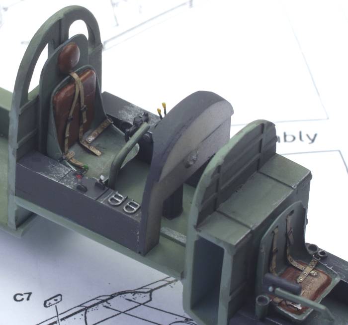
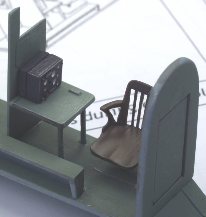
fuselage I added all of the seats, consoles and other various details
supplied for the interior. I added some PE levers from my spares box
as
I thought it would dress things up a bit. The pilot's seat location
was
a bit ambiguous on the instructions so I used a pilot figure to
position it height wise. From the instruction sheet it looked like it
was setting on the floor but at that level the pilots eyes would have
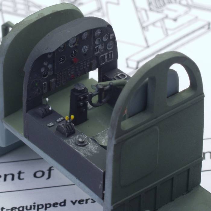
been below the instrument panel. I added a few instrument decals to
the
instrument panel and high lighted the raised detail with a silver
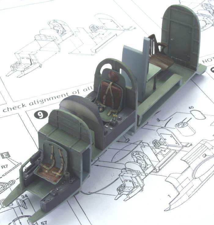
pencil. Seat belts and harnesses also came from the spares box. Once
every thing was installed I gave the visible interior parts a sludge
wash and it was ready to be inserted in the fuselage. See photos
below.
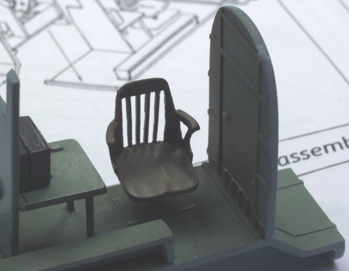
One of the things I found after taking the above photos was that there were glazings to fit into the openings behind the pilot. This makes sense as it would otherwise become quite drafty, especially on the versions with an open gun position. The instructions do not mention them at all. One side seemed a bit larger than the other and one piece seemed to fit better in one place than the other. I glued them in place with clear parts cement then brushed them with future after they dried.
As usual when I went to assemble the fuselage I found that the entire interior assembly seemed too long. If I positioned the rear bulkhead for the radio room in a position to allow the turret to fit then the pilots rear bulkhead sat forward of the fuselage opening and the floor for the bombardier extended out beyond the edge of the nose glazing. It appeared that the best fix for this would be to break the connection where the pilots rear bulkhead met the radio room floor and reglue it about an eighth of an inch back from where it was. This seemed to take care of that issue. There are no locators for the interior on the fuselage walls so I positioned it where I thought it should go and held it in place with some silly putty and used some five minute epoxy to attach it to the fuselage. Once this was set I glued the fuselage halves together. There was a gap around the top of the pilots rear bulkhead that would show through the canopy so I filled it with some Magic Sculpt and when dry painted it.
From August of 2008 till early in 2015 this kit saw only occasional attention due to a number of factors but mostly due to frustrations with short comings of the kit. While one expects some difficulties to be encountered with limited run kits this one seem to be just one thing after another making it difficult to maintain my interest in it.
The fuselage and wing assemblies were relatively uneventful although I should have checked the cockpit and nose glazing before hand as they were both too wide and it would have been easy to add a spacer between the halves if I had. The wings and tail were both just butt joints but there was a lot of surface area there and I chose not to uses pins to strengthen these joints and once glued I had no issues with them.
One issue that was not all that uncommon but seemed to occupy way more time than it should have was fitting the engines into the cowlings. I spent a lot of time painting and detailing the engines only to find they were too large to fit the cowlings. The choices were to grind down the cylinder heads or grind away the insides of the cowlings. Since I couldn't bring myself to grind the nicely detailed engines I chose the latter. Fortunately the cowlings were thick and there was little danger in breaking through them. It did require a lot of time to remove the necessary material even using a Dremel tool. One needs to be somewhat careful with this step as the only thing that the cowlings attach to is the engine cylinders. Grind away too much and you'll have other problems to deal with. By the time I got both engines fit as best I could I had again tired of the kit and it went back on the shelf.
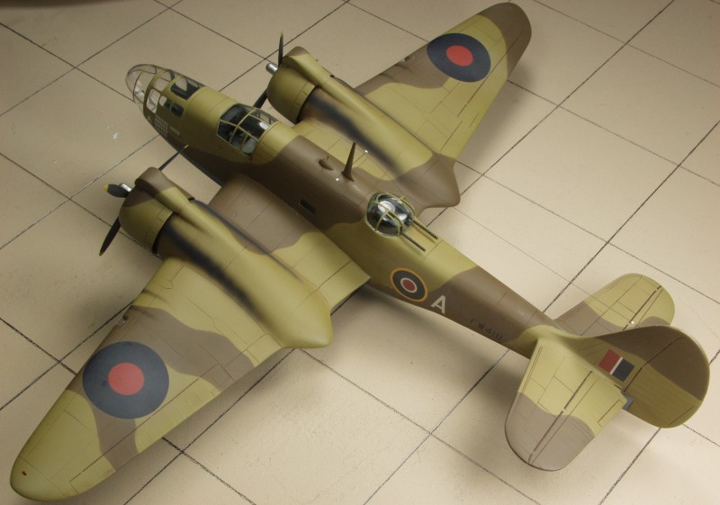
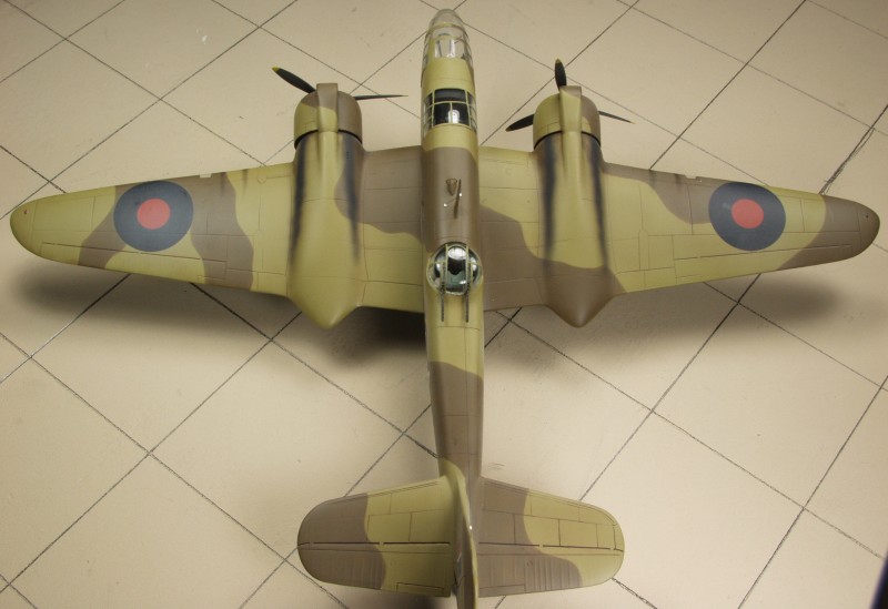
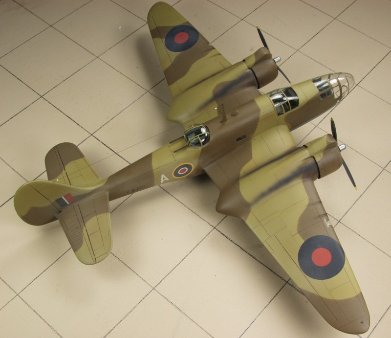
Early in 2015 I started working on the smaller Maryland kit by Special Hobby and forced myself to get back on this I immediately ran into more issues with the engines and cowlings. The engines glue to a blob of plastic that spaces it out from wing the correct distance. Unfortunately there is no index tabs or any other reference for mounting the blob to the wing, just a flat surface against a flat surface. I managed to get one engine correctly located but ended up gluing and removing the other three times and still didn't get it dead on but that issue didn't show up till later. A large engine intake scoop needs to be mounted to the top of the cowling and there were index marks for this on the cowling and the intakes actually fit pretty good considering some complex geometry. When it came time to mount the cowlings I found that the intakes did not align well with the balance of the intake trunk located on the wing. Part of this was due to the earlier engine mount routine. It took a lot of fussing and fitting to get it all close but again the slight misalignment of the one engine bit me when I mounted the oil cooler below the engines. The visible part of the coolers were not the same from side to side but at this point I had had enough of this silliness and left it as it was. I also spent a lot of time fiddling with the clear parts and was never totally satisfied with the final fit. Even the landing gear attachment was poorly designed and fit was problematic and a pita to get the fit right. Never the less I did finally finish it. The last throws of assembly were not well documented. In any event it was finished, the completed photos follow.
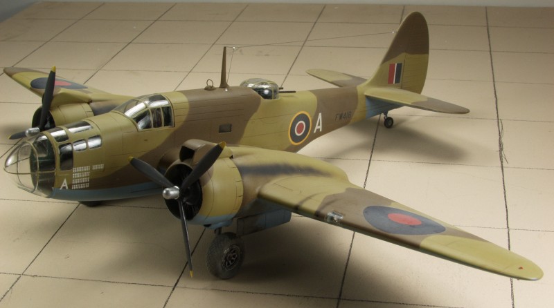
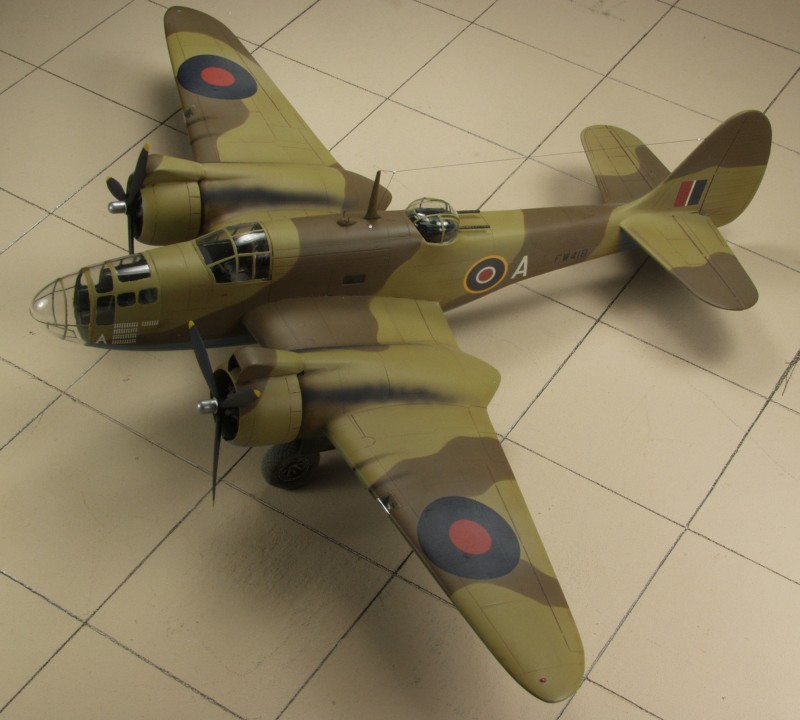
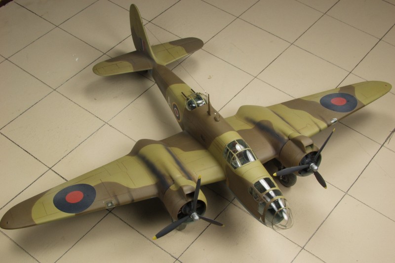
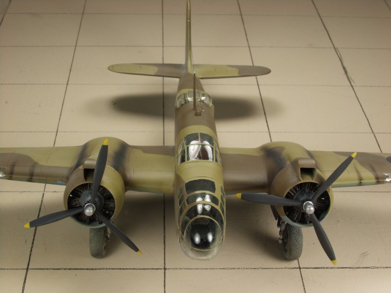
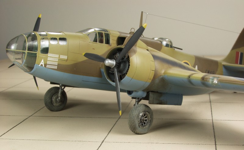
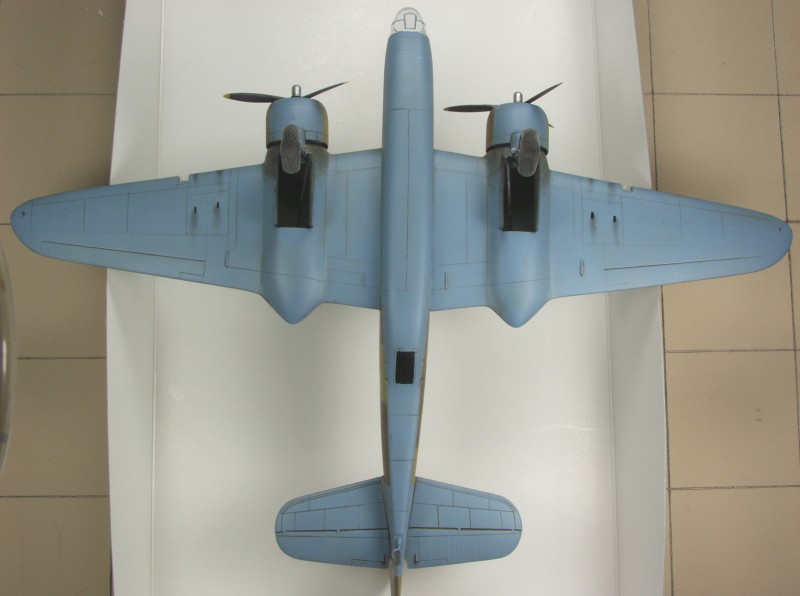
For the most part I like Classic Airframes kits but this one seemed to be the bane of my existence and was not a fun build but in the end it came out OK, not great but OK.
Back to the MISC BRITISH page
Updated 2/13/16One of the things I found after taking the above photos was that there were glazings to fit into the openings behind the pilot. This makes sense as it would otherwise become quite drafty, especially on the versions with an open gun position. The instructions do not mention them at all. One side seemed a bit larger than the other and one piece seemed to fit better in one place than the other. I glued them in place with clear parts cement then brushed them with future after they dried.
As usual when I went to assemble the fuselage I found that the entire interior assembly seemed too long. If I positioned the rear bulkhead for the radio room in a position to allow the turret to fit then the pilots rear bulkhead sat forward of the fuselage opening and the floor for the bombardier extended out beyond the edge of the nose glazing. It appeared that the best fix for this would be to break the connection where the pilots rear bulkhead met the radio room floor and reglue it about an eighth of an inch back from where it was. This seemed to take care of that issue. There are no locators for the interior on the fuselage walls so I positioned it where I thought it should go and held it in place with some silly putty and used some five minute epoxy to attach it to the fuselage. Once this was set I glued the fuselage halves together. There was a gap around the top of the pilots rear bulkhead that would show through the canopy so I filled it with some Magic Sculpt and when dry painted it.
From August of 2008 till early in 2015 this kit saw only occasional attention due to a number of factors but mostly due to frustrations with short comings of the kit. While one expects some difficulties to be encountered with limited run kits this one seem to be just one thing after another making it difficult to maintain my interest in it.
The fuselage and wing assemblies were relatively uneventful although I should have checked the cockpit and nose glazing before hand as they were both too wide and it would have been easy to add a spacer between the halves if I had. The wings and tail were both just butt joints but there was a lot of surface area there and I chose not to uses pins to strengthen these joints and once glued I had no issues with them.
One issue that was not all that uncommon but seemed to occupy way more time than it should have was fitting the engines into the cowlings. I spent a lot of time painting and detailing the engines only to find they were too large to fit the cowlings. The choices were to grind down the cylinder heads or grind away the insides of the cowlings. Since I couldn't bring myself to grind the nicely detailed engines I chose the latter. Fortunately the cowlings were thick and there was little danger in breaking through them. It did require a lot of time to remove the necessary material even using a Dremel tool. One needs to be somewhat careful with this step as the only thing that the cowlings attach to is the engine cylinders. Grind away too much and you'll have other problems to deal with. By the time I got both engines fit as best I could I had again tired of the kit and it went back on the shelf.
Early in 2015 I started working on the smaller Maryland kit by Special Hobby and forced myself to get back on this I immediately ran into more issues with the engines and cowlings. The engines glue to a blob of plastic that spaces it out from wing the correct distance. Unfortunately there is no index tabs or any other reference for mounting the blob to the wing, just a flat surface against a flat surface. I managed to get one engine correctly located but ended up gluing and removing the other three times and still didn't get it dead on but that issue didn't show up till later. A large engine intake scoop needs to be mounted to the top of the cowling and there were index marks for this on the cowling and the intakes actually fit pretty good considering some complex geometry. When it came time to mount the cowlings I found that the intakes did not align well with the balance of the intake trunk located on the wing. Part of this was due to the earlier engine mount routine. It took a lot of fussing and fitting to get it all close but again the slight misalignment of the one engine bit me when I mounted the oil cooler below the engines. The visible part of the coolers were not the same from side to side but at this point I had had enough of this silliness and left it as it was. I also spent a lot of time fiddling with the clear parts and was never totally satisfied with the final fit. Even the landing gear attachment was poorly designed and fit was problematic and a pita to get the fit right. Never the less I did finally finish it. The last throws of assembly were not well documented. In any event it was finished, the completed photos follow.
For the most part I like Classic Airframes kits but this one seemed to be the bane of my existence and was not a fun build but in the end it came out OK, not great but OK.
Back to the MISC BRITISH page