
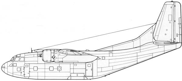
C-123B
The C-123 provider was designed originally as an assault glider aircraft for the United States Air Force by Chase Aircraft as the XCG-20. Two powered variants of the XCG-20 were developed during the early 1950s, as the XC-123 and XC-123A. The only difference between the two was the type of engines used. The XC-123 used two Pratt & Whitney R-2800-23 air-cooled radial piston engines, while the XC-123A was fitted with four General Electric J47-GE-11 turbojets, in two pods. The XC-123A also has the distinction, while only experimental, of being the USAF first jet-powered military transport. While the piston-powered XC-123 was initially well regarded for tactical transport for its ruggedness and reliability and ability to operate from short and unimproved airstrips, the turbojet-powered XC-123A - designed for high-speed transport between USAF bases for critical parts and personnel - was found unable to operate from short and rough airstrips. There was also no practical speed advantage due to the wing and fuselage design, and a drastic reduction in range. Only the one turbojet-powered test and evaluation version was built.
The C-123B was the production model based on the XC-123 with two 2300 hp R-2800-99W engines with accommodation for 61 troops or 50 stretchers, five built by Chase and 302 build by Fairchild Aircraft. For more information about this aircraft search the Internet.
The Kit
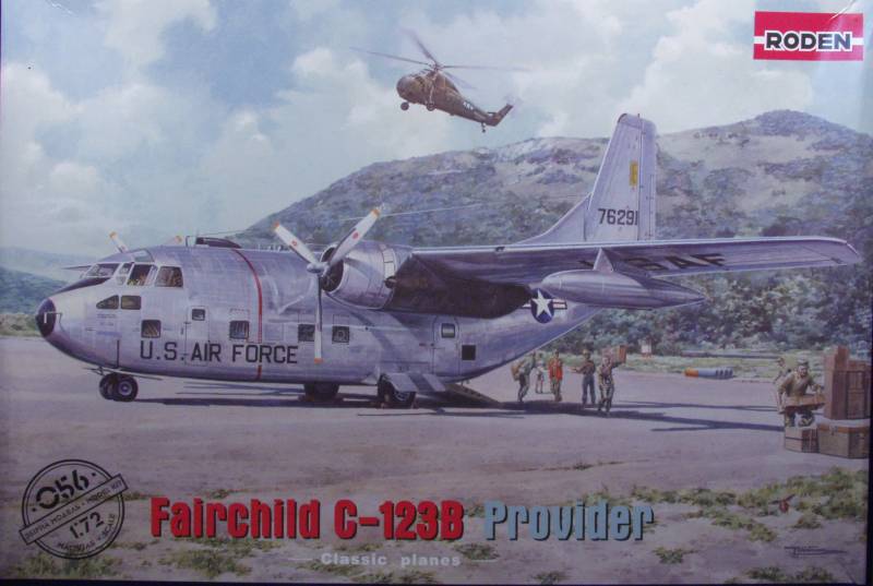
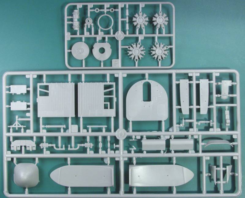
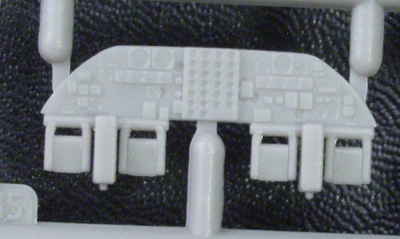
From a detail stand point the cockpit is well appointed for the scale with seats, consoles, side panels and various other details. The inside of the fuselage has rib detail molded in but is otherwise relatively spartan with a floor some bulkheads and duct work and what appears to jump seats. No effort was made to model the navigators station which was just behind the cockpit. There are also a few ejector pin marks that will need to be fixed if you want to leave the rear cargo door open. The wheel wells and landing gear are nicely detailed and the engines are fairly complete for the scale and include both rows of the R2800's cylinders but it's doubtful you'll ever see much of the rear jugs. There are separate cowl flaps for the cowlings. All the window glazing are separate. I did not try fitting them but if they don't fit well it's going to add a lot of work to the kit. The kit comes with under wing tanks and a lot of antennas and other fiddly bits to stick on the outside. OK lets take a look at the sprues. Note duplicate sprues are not shown.
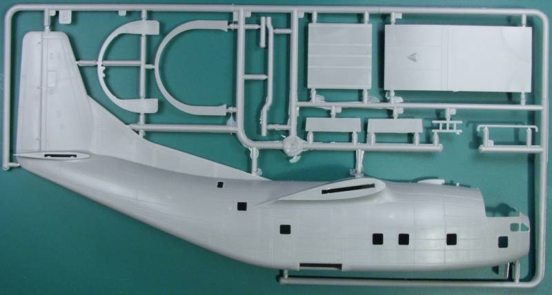
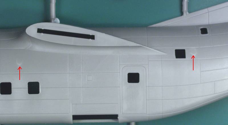
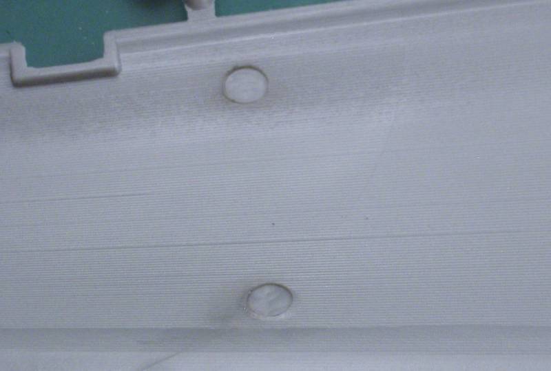
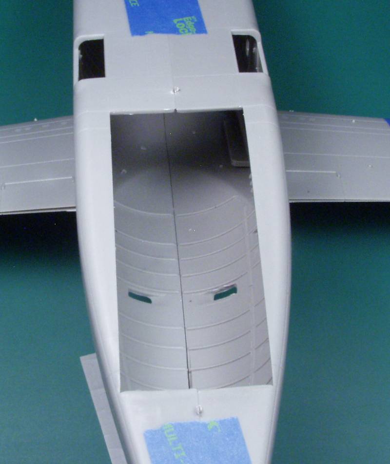
The next photo shows the interior rib detail and yes there are few ejector pin marks but I have seen worse.
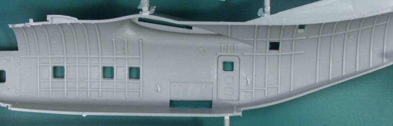
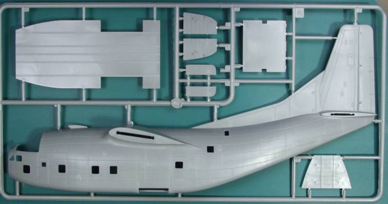

The big hole in the bottom for the cargo ramp and door.
The clear parts are reasonably thin and clear but a few of the panes in the cockpit glass had some distortion. The frame line are well delineated and the areas to be painted are frosted.
![]()
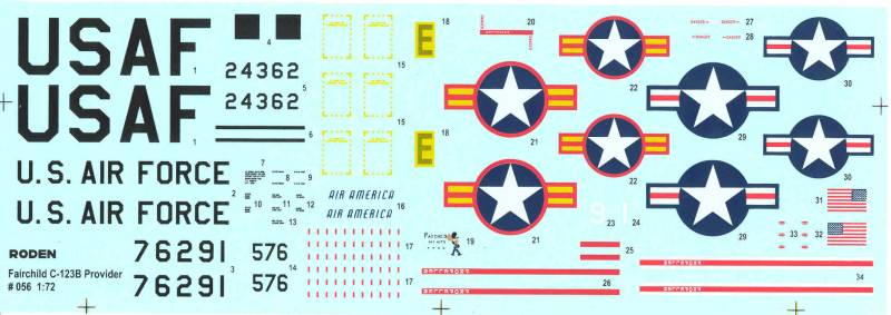
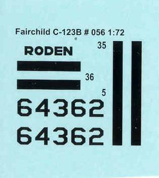
The decals are thin, glossy, opaque and pretty well registered but the two US flags are not all that well printed. The sheet has markings for three aircraft, all three in natural metal, the first a USAF from Vietnam early 1964, the second from the VNAF from 1964 and the third an Air America aircraft serving in Thailand during 1966. The sheet has a fair number of stencils. I have no experience with Roden decals but have read a number of not so favorable comments about them. I suspect we'll see some after market decals for these as I would prefer to do one in SEA camo anyway.
The instructions are three sheets folded to create 12 pages. They contain a brief multilingual history, a parts map, the usual warnings, icon chart, paint list, six and one half pages of assembly diagrams and three pages of marking instructions.
After Market Goodies
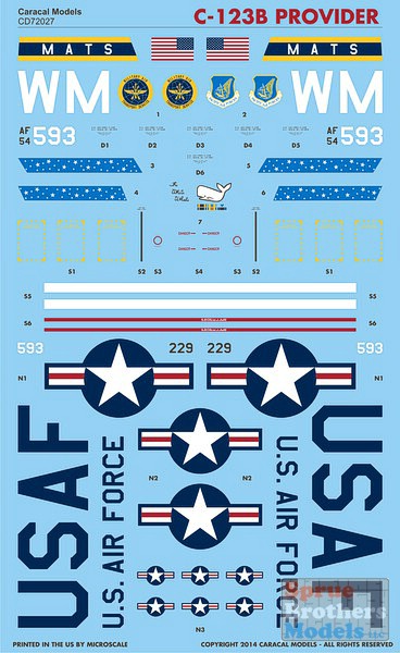
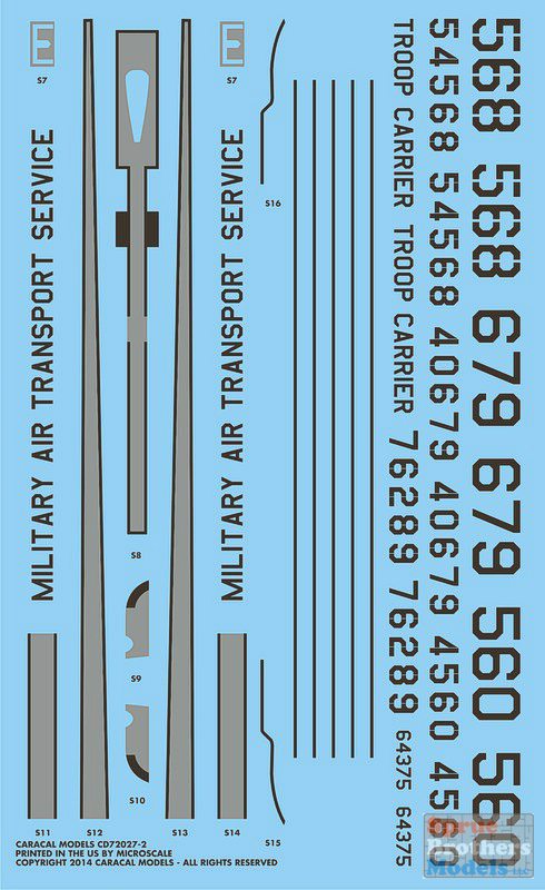
Nothing at the time of this review and not much other than decals and white metal replacements for the landing gear have been released since. I opted to go with Caracal decals CD 72027. I forgot to get a scan of these before using them so I borrowed a couple from Sprue Brothers. These are made by Microscale and worked as expected.
Conclusions
While I may have sounded
rather critical of the kit, I'm actually quite pleased with it.
Not my
scale of choice, but probably a good compromise for the size of
the kit
as it has an 18 1/2" wing span in 1/72. The only other injection
kit in
this scale is the horrible Mach 2 kit and while I don't have that
one I
do have several of their other kits and they are all very
laborious
builds, this one is way better than those. The major pieces fit
together nicely and it should build into a nice model, it just
needs to
be treated like a limited run kit.
Links to kit
build or reviews
A nice in box review with a different opinion on the panel lines can be found here.
References
Back to the MISCELLANEOUS 1/72 page
The Build
As I mentioned in the conclusions above this kit does need to be treated like a limited run kit and you will see why as we go along. While the large parts fit reasonably well the smaller parts do not follow suit. I've found that though many parts have alignment pins, either the holes are too large or too small. A couple things I found irritating... The rear cargo door has no option for mounting it closed. There is nothing to hold it in place. I will probably end up gluing it to one half of the fuselage before gluing the halves together. It was also not shaped quite right but because of the softness of the plastic I was able to bend it a bit to fit. Irritation number two was the clear parts did not fit well. I ended up carving or sanding some on almost every one. To make it worse on about about half of them the sprue attachment points overlapped the mounting ridge on the part and cleaning it out of the ridge was not fun. I mentioned above the softness of the plastic, this and some of the large sprue attachment points and the mold misalignment on many of the smaller parts made clean up a chore.
First up the cockpit, OK level of detail for 1/72 as far as I'm concerned. The canopy is not super clear so anything inside will not be all that visible any way. The IP is set back under the cowl and the indentations for the instruments were mostly too small for the instrument decals I had and the kit decals did not provide a panel so I just painted it black. I did add belts and harnesses to the seats.
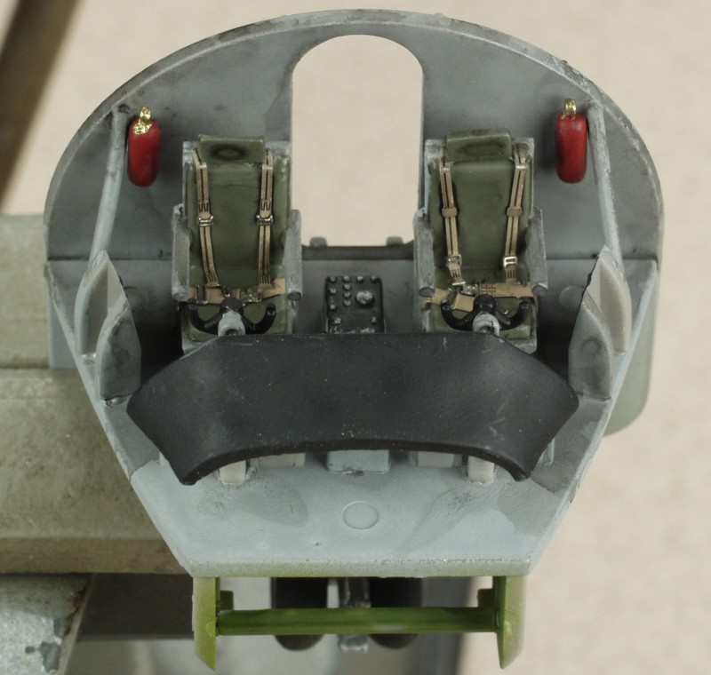
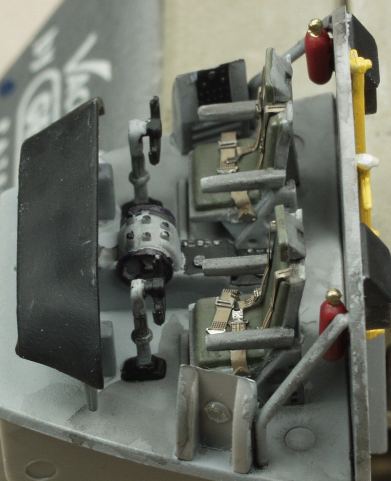
Looks pretty ugly up close but OK through the cockpit windows. The nose wheel well is just below the cockpit and is part of the same assembly. The nose gear is pretty well detailed but about all you'll see in the end are the wheels themselves. I replaced the kit parts for the two small diameter struts with some brass wire as the kit parts were just too hard to clean up and make round. When I test fit this assembly in the fuselage I found there was an interference fit with the torque scissors but by clipping the tip of it off it provided an additional support point which is handy as the gear seems a bit wimpy for the task. The overall weakness, soft plastic and needed to install it before painting would come back to haunt me later.
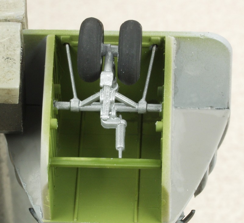
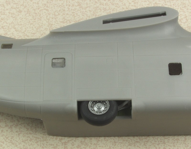
Speaking of the gear, the main gear are shown next. First off the wheels were a sloppy fit on the axles. I drilled them out, plugged the hole with some styrene rod and redrilled. As you can see in the photo the gear are quite long and have only a small mounting point at the bottom and a link connecting it to at the top. I reinforced the bottom point with CA and after noting how much flex there was also glued the top to the side wall for extra strength. This seemed to make them fairly solid but after mounting the gear bays in the fuselage I found when checking to see how much weight to add to the nose, that the axles actually flexed under the weight of the plane. Short of ripping it all apart and finding an alternative I resorted to gluing a block of styrene between the inside of the wheel and the fuselage. This seems to have strengthened every thing so the wheels don't cant outward with the weight of the plane on them and painted black they will not be that noticeable. One can only see the bottom 2/3 of the wheel once installed.
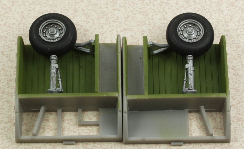
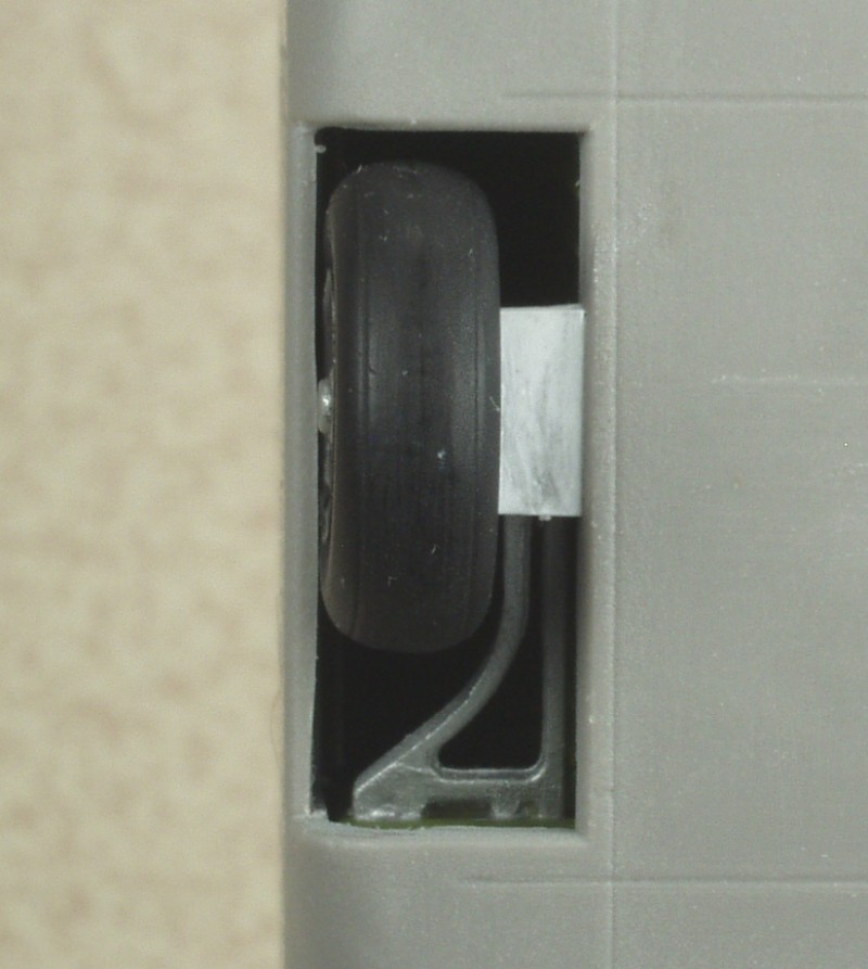
If I had to do this over again I would just glue a block of styrene to the wheel well and drill through the wheel and pin it to the block and forget about the struts.
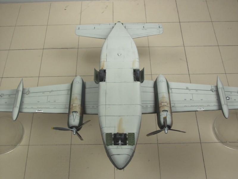
Speaking of nose weight, this thing is seriously tail heavy. The instruction say 40 grams in the nose cone. It didn't look like 40 would fit in the nose cone so I opted to put some behind the cockpit. Even leaving out all of the interior detail aft of the landing gear it took about 70 grams to make it a solid nose sitter. During this process I think I found why they want you to leave the back door open. It's the only way I can see that you could possibly align all the innards when assembling the fuselage. Since near as I could tell, none of the interior detail adds any strength to the assembly, I left it all out. Can't see it, doesn't need to be there !
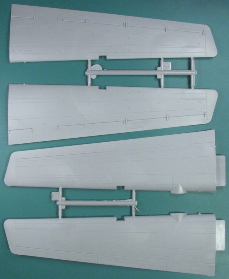
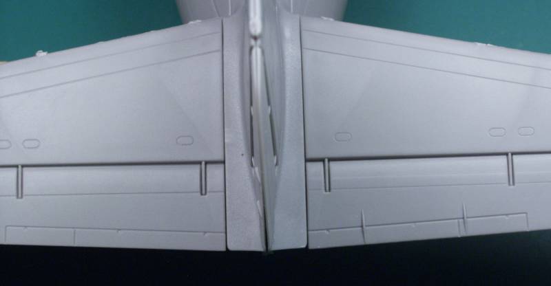
The wings and tail parts were assembled, these went together with no issues, a little flash to deal with and some holes that need to be drilled in the bottom wing halves before assembly. I found it strange they provide the holes for the sway braces for the wing tanks but not the mounting holes for the tanks themselves.
The engines proved to be a major PITA. Each engine is a kit in its self, two rows of cylinders, each in two halves, separate intake and exhaust manifolds, separate crankcase, engine accessory section, rear firewall, center bulkhead, propeller shaft, etc. In this scale a molded engine front would have satisfied my needs. So first step is to assemble the eight cylinder bank halves. So what do I find...
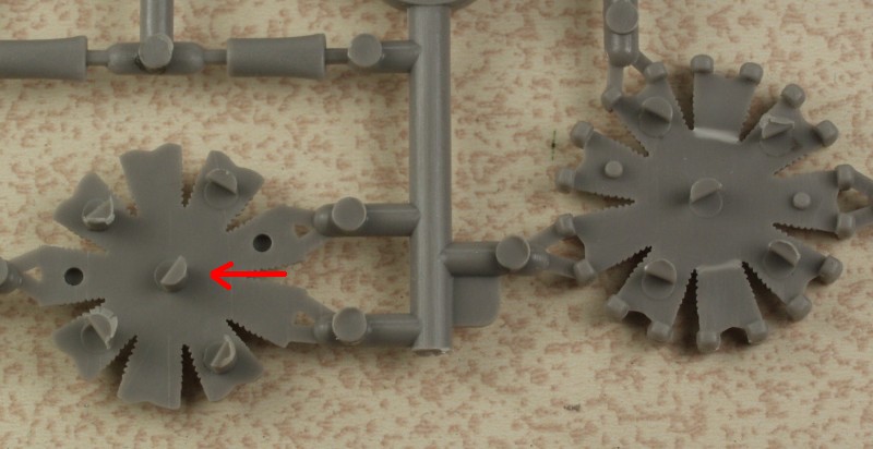
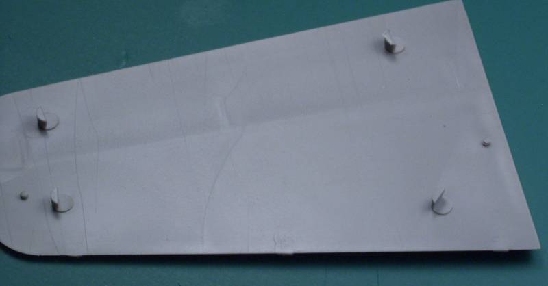
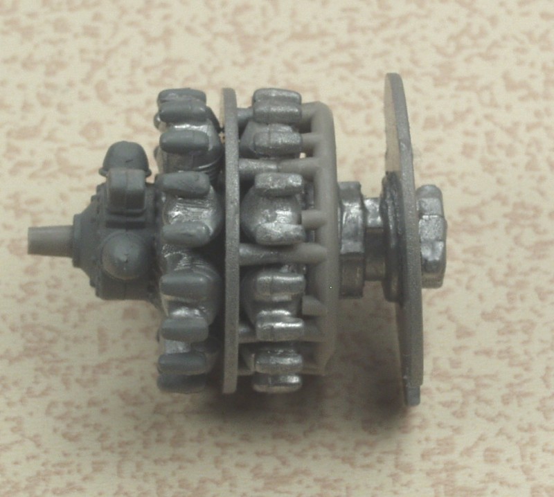
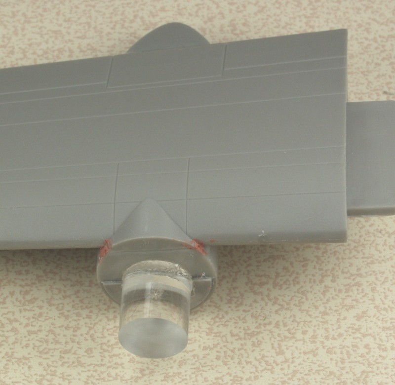
On the back of each half are five ejector towers as indicated by the red line in the photo. On the back half, no problem, snip them off with sprue cutter and a quick swipe on some sandpaper and done. On the forward half the rocker covers protrude, blocking one from getting the sprue cutters in to cut flush and making it difficult to trim what is left flush to get a tight fit between the two. To top it off the two alignment pins which orient the alignment part on the opposite side to kept the banks in proper position don't do a good job of aligning the cylinders themselves. These go together OK for the most part with the exception of the engine accessory section which was poorly molded. It didn't fit well into the opening for it in the rear of the engine and the rear firewall didn't fit well to it. Unfortunately the rear firewall is the mounting point for the engine into the cowling. You can see in the photo that it is not sitting straight in spite of all efforts to make it so.
When I tried to test fit it into the cowling the first thing I noticed was that the two notches in the firewall were too small to clear the exhaust bulges inside the cowling. These were made bigger to get it to fit per the instructions but I found that this position left the front of the engine recessed too far from the front for proper fitments of the propellers. I tried to solve this by fitting it forward of the intended mounting ledge. This fixed the depth issue but I found I could not get the engine centered in the cowling. After I spent an inordinate amount of time shimming and fussing with this to no avail and came close to shoving the whole works back into the box. I finally walked away for while and conjured up another scheme.
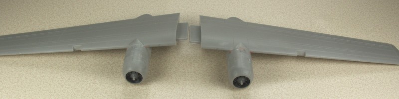
I cut the accessory section off even with the exhaust manifold. The manifold is still needed to mount the exhausts. Through trial and error I determined how long of a spacer I would need to attach the engine to the mounting point on the front of the wing. I had some 1/2" diameter Plexiglas rod in my material larder and I used it to make up spacers. When I found the right length I glued them to the wing as shown in the next photo.
The cowls were then glued to the wing and once set I put a big glob of slow setting tube glue to the back of the engine, set it in place on the spacer then attached the cowl front. Once the front was set ,I tweaked the engines into place then let everything set up over night. Finally assembly of the wings shown below.
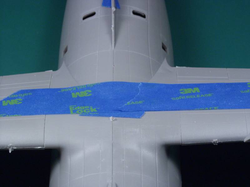
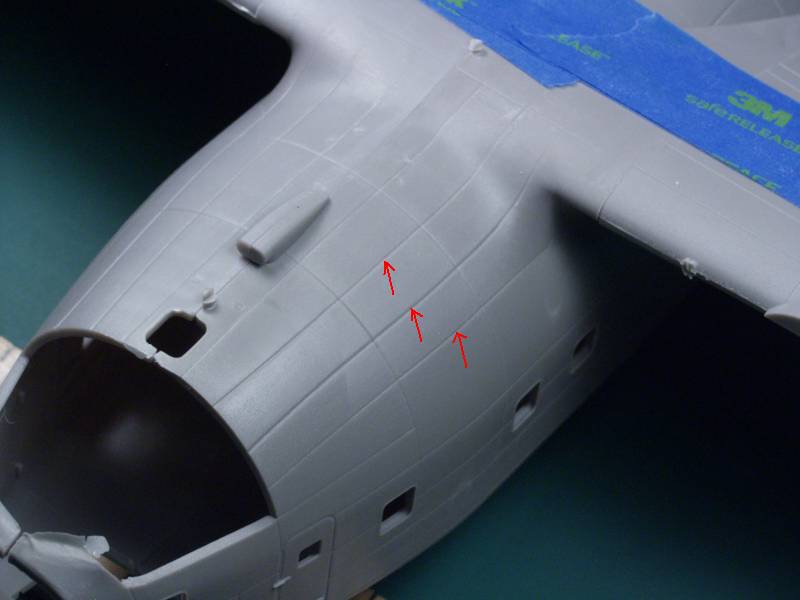
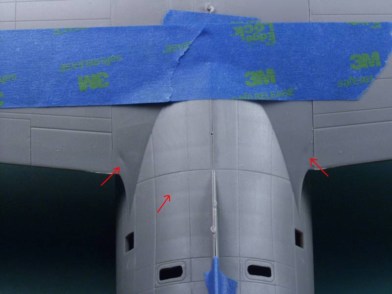
The fuselage went together relatively easy, I did it as a progressive glue to get each section aligned as well as possible before doing the next. I did use clamps in a couple places and the area around the rear door was the worst to deal with. I manage to break off the nose gear in the process but I'm going to wait till after the painting is done before fixing it. This is one kit that would benefit from some metal landing gear. After doing the worst of the seam work I glued the wings and tail on. The wings wanted to droop into an slight negative dihedral situation but checking drawings shows that it did have a bit of negative dihedral. Fit of the wings and tail was quite good. A little body work to do before paint and I need to finish masking the main canopy. I really missed not having a mask set.
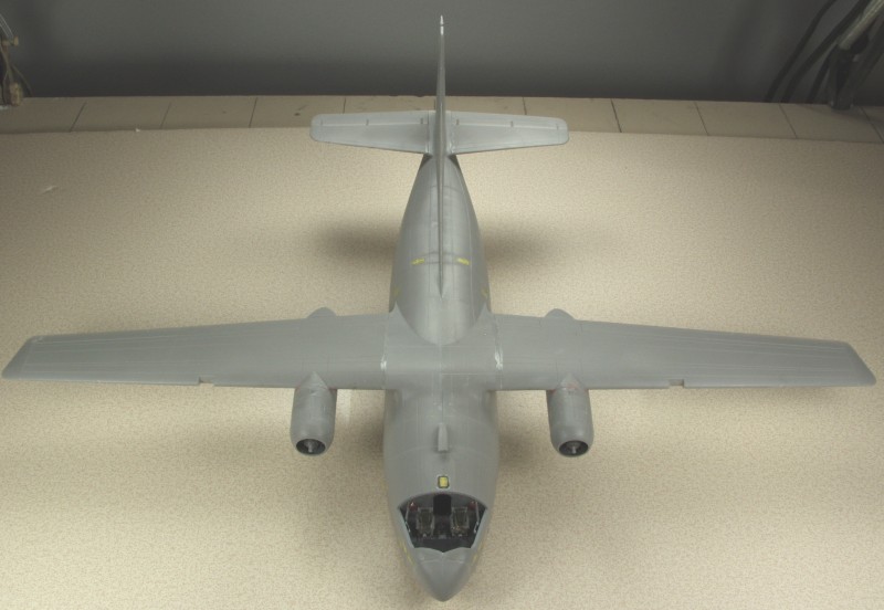
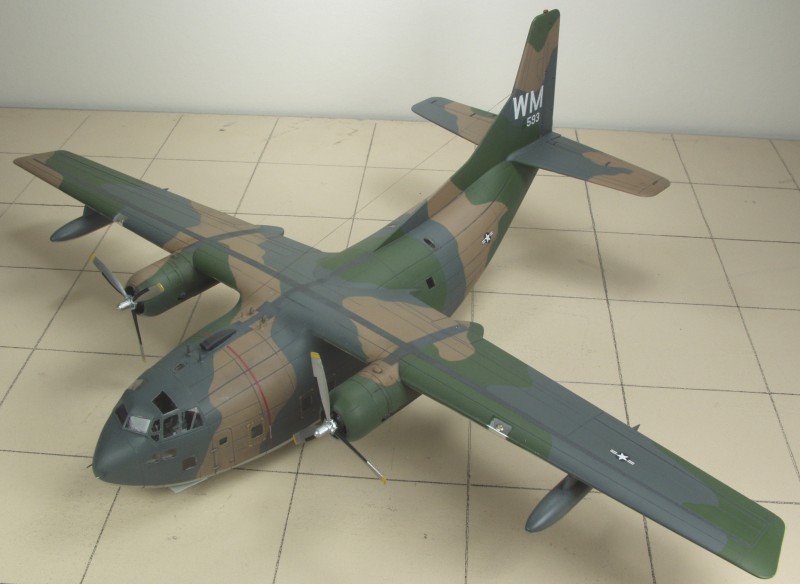
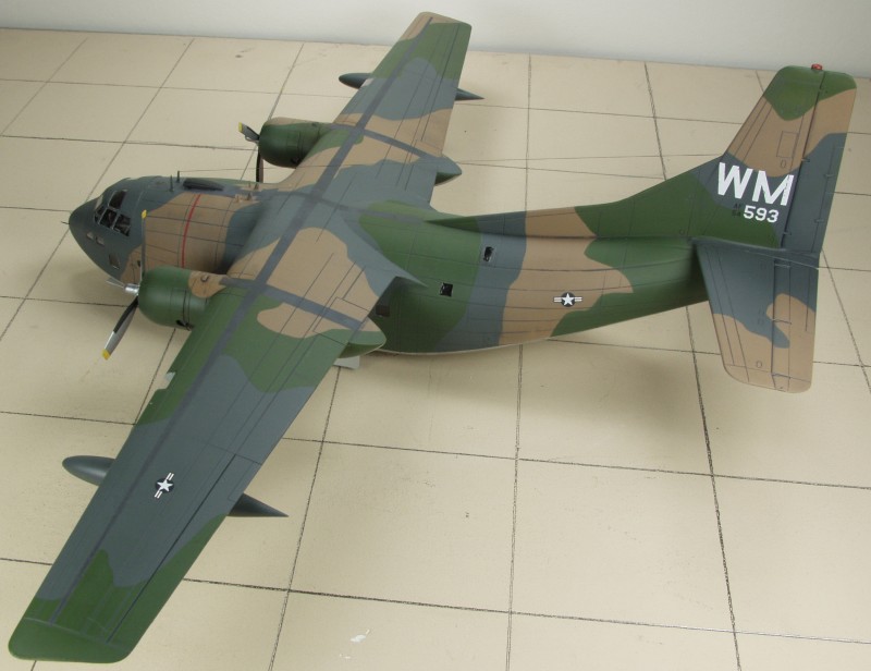
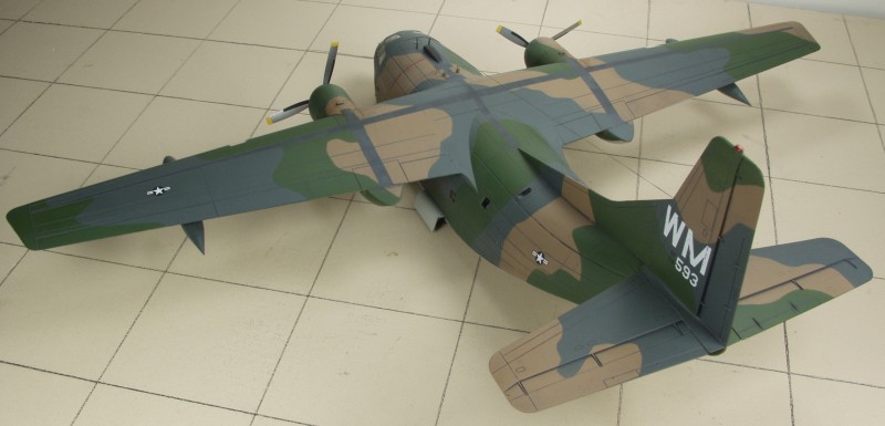
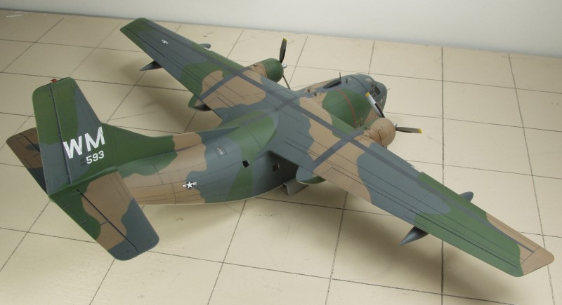
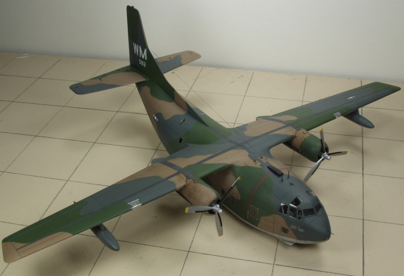
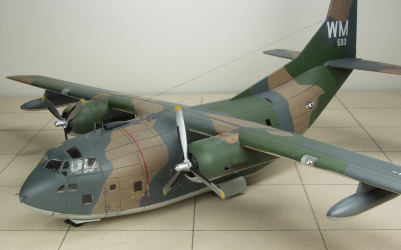
Colors on, ready for a clear coat and decals...
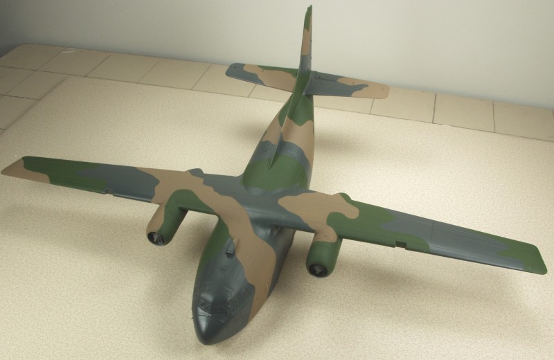
All finished although at points it was a struggle. The after market decals were a treat and went on beautifully. I did manage to break loose one of the main gears while putting on the decals and in the end needed to strengthen it with a small brass pin. Fixing the nose gear was also a struggle and a pin was used there as well. The plastic is just too soft and small in section. I cheated in a couple of places. The wing tank sway braces were poorly formed, the mounting holes too big and there no mating oles in the pylons so I just tossed them. Unless you go looking for them, you'll never know they are missing. I added MV lenses for the landing lights and since the clear covers didn't fit I tossed them and used packing tape.
Back to the MISCELLANEOUS 1/72 page