
P-70
The P-70 was a
"stopgap" solution to providing a night fighter during the protracted
development period of the P-61. It was modification of the A-20 attack
bomber. The prototype began life as an A-20 (39-735) and was adapted
for night fighting duties under the designation XP-70. Two
non-supercharged 1600 hp Wright R-2600-11s replaced the turbo
supercharged R-2600-7s. RAF experience with the modified DB-7 Havoc
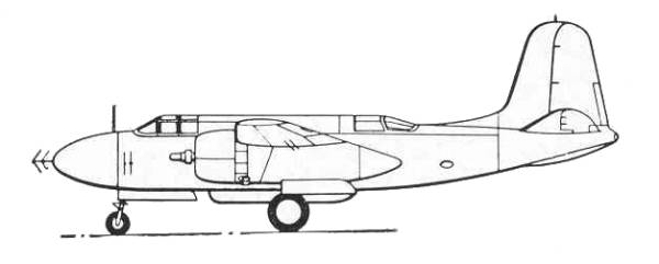
was used as a guideline. British AI Mk IV radar was mounted in an
unglazed nose, with an arrow-like transmitting antenna located in
front of the nose, the azimuth antenna located on both sides of the
fuselage and the elevation antenna mounted above and below the left
wing.. All bomb racks and all defensive armament were removed. The
crew was reduced from three to two, the second crewman being a radar
operator seated in the rear cockpit. Four 20-mm cannon with 60 rpg
were installed in a ventral tub. Other changes included a 24 volt
electrical system, a 250 gallon fuel tank in the bomb bay and more
extensive crew armor plate was provided
The success of
these modifications led to a USAAC decision on October 15, 1940 to
have fifty-nine more of the A-20s on order modified as P-70 night
fighters. Fifty-nine P-70s, originally ordered as A-20s were completed
with R-2600-11 engines as night fighters. Serials were 39-736 to
39-740, 39-742 to 39-744, 39-746 and 39-747 and 39-749 to 39-797) They
were identical to the XP-70 except for minor equipment changes.
Maximum speed was 329 mph at 14,000 feet. An altitude of 12,000 feet
could be attained in 8 minutes, service ceiling was 28,250 feet, and
combat range was 1060 miles. Weights were 16,031 pounds empty and
20,984 pounds gross. The first P-70 was delivered in April of 1942,
and the order was completed in September of that year.
In 1943
thirty-nine A-20C's were modified to P-70A-1's. They were armed with
six or eight fifty caliber machine guns and improved radar equipment
was installed in the nose.
P-70A-2 was the
designation given to 65 A-20G's that were modified as night fighters.
It retained the battery of forward firing fifty caliber machine guns
but all flexible defensive weapons were removed.
P-70B-1 was a single A-20G modified as an experimental night fighter with the SCR729 centimetric radar in the nose. Armament consisted of six fifty caliber machine guns mounted in three blisters on each side of the nose.
The P-70B-2 was
a group of 105 A-20G's and A-20J's modified as night fighter
trainers Six to eight fifty caliber machine guns could be carried in a
ventral tray but were not always fitted.
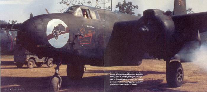
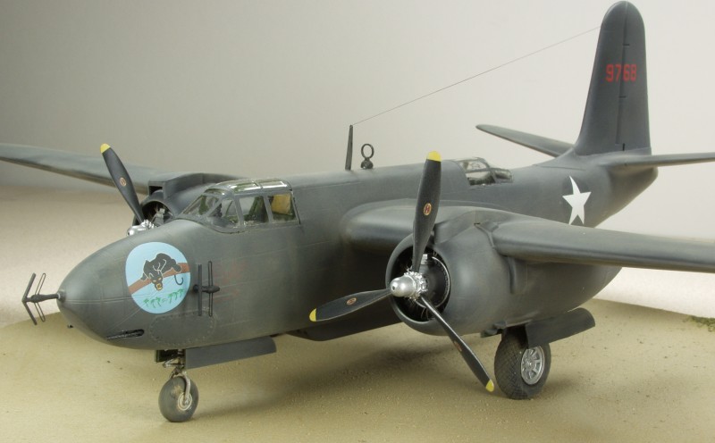
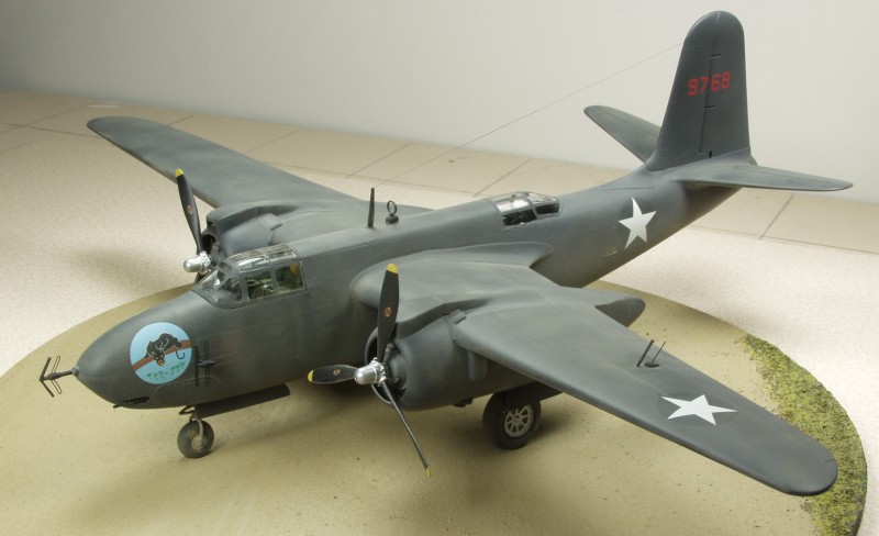
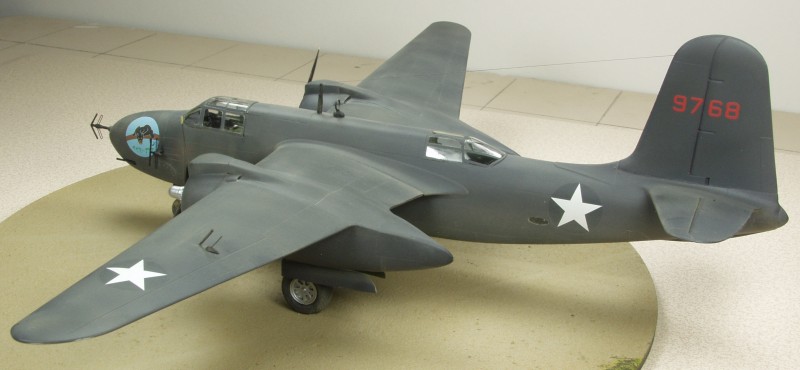
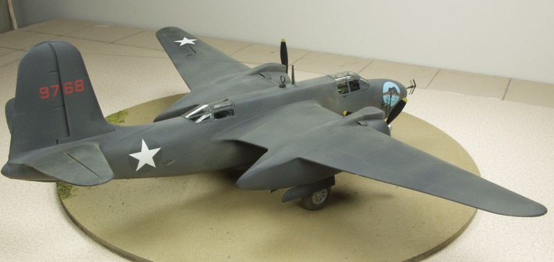
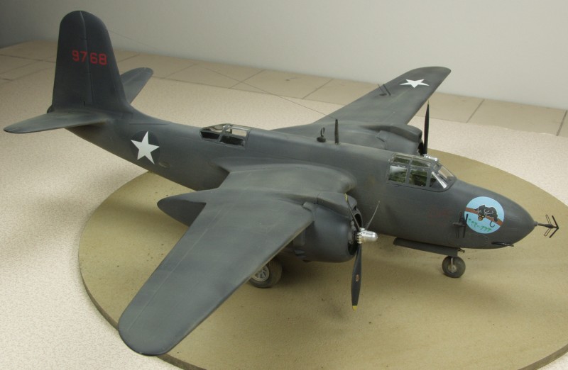
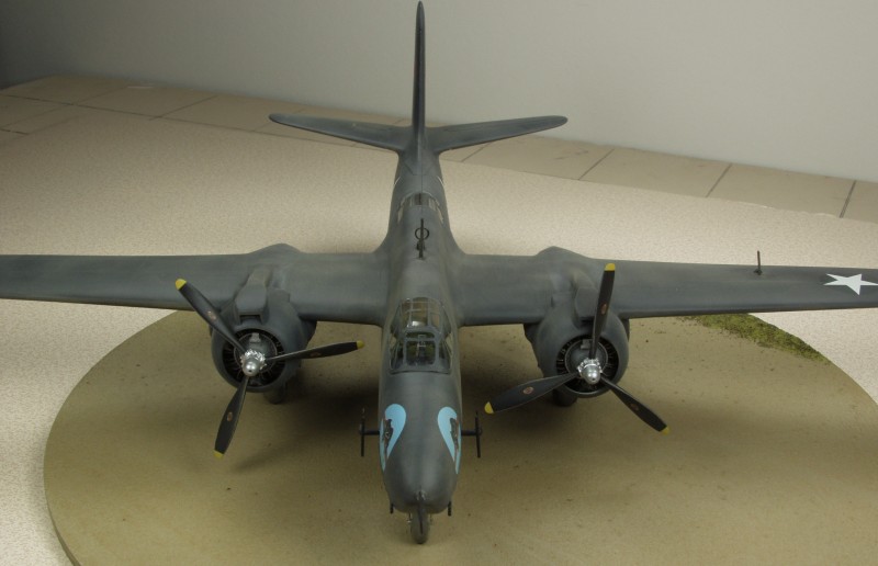
The entire aircraft was painted flat black as were the early British counterparts of the day. The first units deployed were sent to the Pacific theater. At this time everything was new. Not just the equipment but the crews and the concept of GCI (ground control intercept) as well. It took upper level commanders a while to understand the requirements for successful operation and during that period of time not a lot of success was had. Two problems came to light early on. One was the reliability of the airborne intercept radar gear which tended to be unreliable above 22,000 feet and the other the ability of the P70 to attain altitudes above 27,000 feet. It didn't take long for the Japanese to figure that out and operate at altitudes around 30,000 feet. Short comings of the P-70 and associated problems with equipment and the learning curve involved with it resulted in relatively little success and many of the aircraft ended up being used for intruder and bombing missions.
The Kit
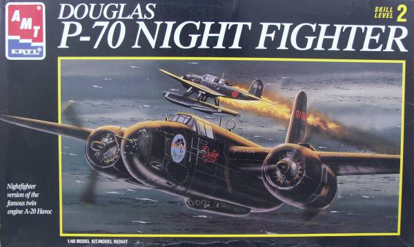
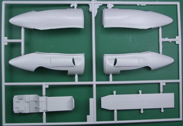
Before beginning the review for this kit I want to note some things about the kit. The artwork on the box, which utilizes one set of the kit supplied decals, shows a different style nose than what is supplied and would be more like what was used on the P-70A-2 except that it should have more than two machine guns in the nose and no ventral tub. Also the box art shows short air intakes on the top of the cowling but the kit supples the correct longer intakes. I suspect lack of documentation was the reason that no radar operator equipment was supplied. The kit decals for the box art version version has the correct serial number to represent one of the original P-70's. A photo published in the October 2008 issue of Flight Journal shows a P-70 in the markings provided in the kit with the nose configuration provided in the kit and it appears that AMT did their homework. The box art itself is still incorrect as it shows a different style nose but at least one can build the kit using the supplied markings with the confidence it represents an actual aircraft. There are still some missing details that need to be added but that becomes a much more trivial issue. So out of the box will build a pretty accurate aircraft of the one that decals are supplied for. It does not have that antennas that were mounted above and below the port wing but these are easy enough to scratch build.
Now lets look in the box. Note: the review has been revised since it was posted in 2008.
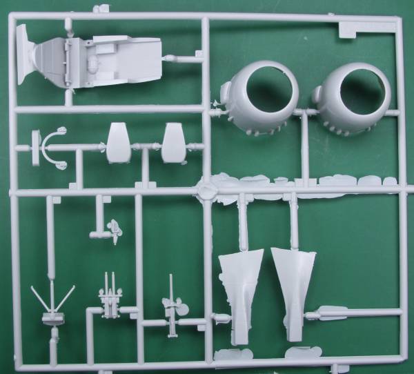
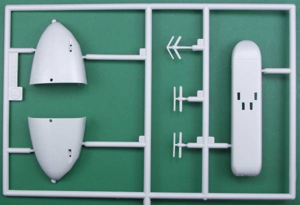
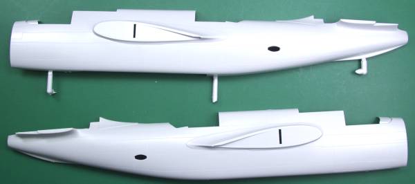
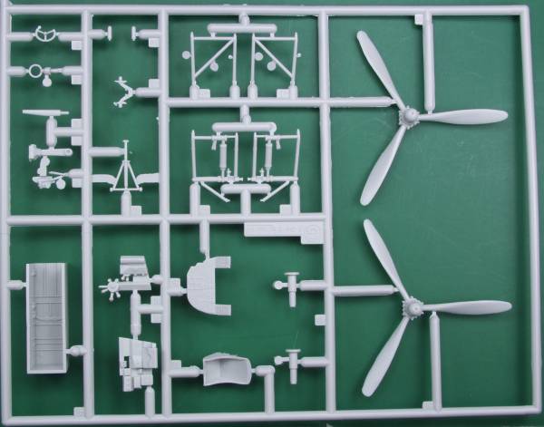
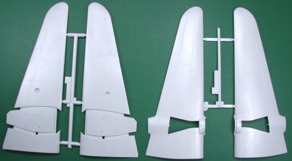
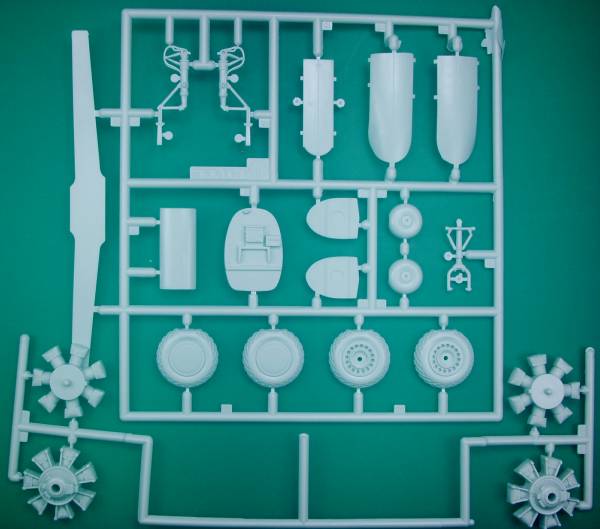
The AMT kit comes in a two part top open box with dramatic artwork of a P70 getting a kill, something that didn't happen much in real life. Inside the box are three bags, two with the parts molded in a light gray color and the other with the clear parts. This kit was derived from the AMT A-20 series of kits and except for a few parts differences is the same kit. The parts have a smooth finish and have fine recessed panel lines. Some of the parts had a moderate amount of flash with one sprue having more than the others. The sprues also appeared to have been cut from a much larger sprue either to fit the box or to separate the specific P-70 parts from the A-20 parts. I did not find any sink holes or other surface defects on the outer surface of the kits and AMT did a good job with ejector pins marks in keeping them where they wouldn't be seen. There are some on the insides of the main gear doors but they line up with the lightening holes on the door so they aren't that noticeable and the ones on the inside of the fuselage aren't in the cockpit area. The cockpit area is moderately detailed but could stand some photo etch to dress it up. One of the issues with the kit is that AMT left out the life raft which was stowed on a shelf directly behind the pilot. Another issue is the exaggerated tire tread pattern they used on the wheels. Fortunately both can be dealt with with after market items discussed later.
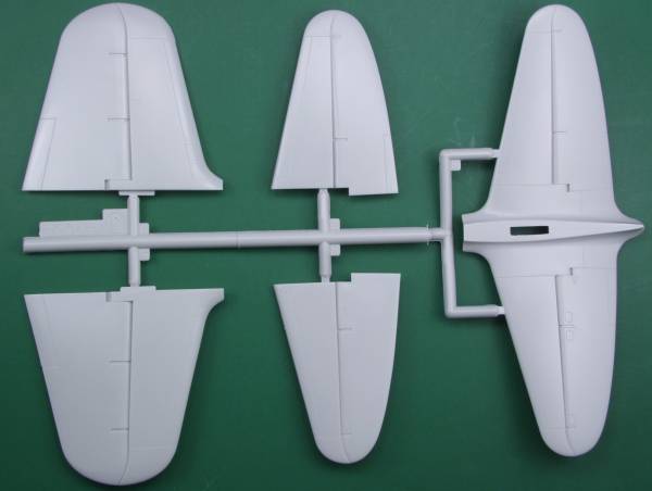
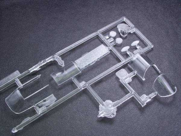
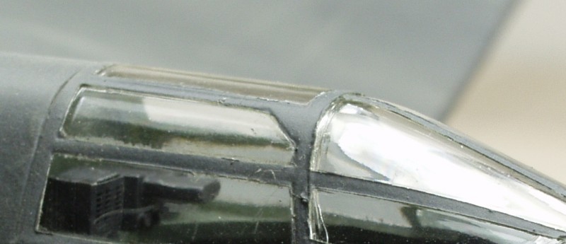
One issue with the kit is that of the radar operators position. In the P-70 he sat in the rear gunners location. AMT include the normal gunners position which comes from the A-20 kit and made no effort to duplicate the radar operators equipment. The landing gear struts are nicely rendered including brake lines. The gear doors are molded in the closed position and need to be cut to use them with the gear down. Mounting them is fiddly as they have mounting tabs but there are no slots to fit them into so it's just a butt joint with the correct alignment left up to the builder. The engines aren't bad but we'll discuss options there as well later in the review. The wheel wells are boxed in and have some detail in them. The shell ejection chutes in the lower gun tub are open but the openings for the guns are just half hearted indentations. There is a spar that fits through the fuselage that will aid in getting the wings set to the proper dihedral. Altogether there are a total of 74 gray pieces. The clear parts are thin but only moderately clear, a coat of Future should help. Both the pilot's canopy and gunners position are two part so they can be displayed in the open position. Altogether there are 9 clear parts bringing the total to 83 parts. See photos below
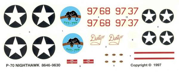
The decals are for two aircraft, one rather plain from 1942 and the other with some nose art from 1943. The one from 1942 matches tail numbers known to be issued to the first 59 aircraft. There was no history provided in the instructions but on the outside of the box it notes that the marking include a P-70 of Detachment A, 6th Night Fighter Squadron based at 3 mile Airstrip, Port Moresby, New Guinea during May of 1943.. Other than the prop manufacturer marking, a fire extinguisher location decal and a propeller warning stripe no other stencils are supplied. Two issues with the decals, on my set the red serial numbers were done over white to make them more opaque but the registration was off allowing a bit of the white to show along one edge like a shadow effect. It bugged me enough that I ended up cutting a stencil and painting them on. The word 'Dusty' did not have a white under layer and as a result when placed on a black surface almost disappeared. Other than these issues the decals worked well. See photo below.
The instructions are printed on a large sheet roughly the size of a "C" size drafting paper that is folded to provide multiple assembly panels. One panel has a color chart with color names and FS numbers and as I mentioned above there is no history or specifications on the instruction sheet. The box top lists the dimensions, weight, horsepower, ceiling, range and armament.
While this kit is no longer available from AMT, Italeri has released the A-20 under their label so it's possible that they may eventually release the P-70 as well. One can only hope that if they do, they did do their homework and supply the necessary parts for an accurate model. Now lets look at some of the after market goodies that can be used with this kit.
After Market Goodies
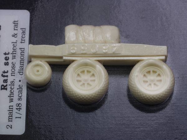
True Details Wheel and Raft set [48059]
As mentioned in the above review two of the issues of the kit are lack of the life raft in the area behind the pilot and the overdone herringbone tread on the tires. In this case both can be problems can be solved with this set. While I'm not real keen on TD wheels, they always look a little too flat to me, in this case they are a major improvement over the kit parts and the raft is a nice bonus. See below.
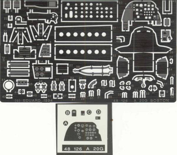
Interior detail photo etch set from Eduard (48-126)
This set and the next one are both sold for the A-20 but will work just fine here. While it's mostly cockpit detail and aimed at the A-20G it does include a few external parts that could be used as well. The instructions are the usual Eduard A4 size page printed on both sides with pictorial diagrams. See below.
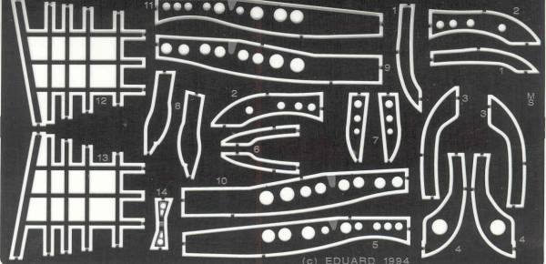
Undercarriage detail photo etch kit from Eduard (48-127)
While titled as undercarriage it's more of a wheel bay detail set which includes a lot of structural details to spruce up the wheel wells, the only undercarriage part is a torque scissors for the nose gear strut. When it came time to utilize this set I found it to be one of the most annoying sets I've ever used. The curved ribs must be edge glued in place making them very weak and trying to get the long pieces with the lightening holes bent to fit just didn't work for me so unless you are dead set on detailed wheel wells, I can't recommend this set. The instructions are an A4 size page printed on one side. See below.
I had planned to use a pair of beautiful Wright 2600 engines from Vector but after checking I would need to grind the tops of the cylinder heads down to below where the push rods attach to the heads and that was too much for me !
This kit will be a tail sitter if one doesn't add weight to the nose area. For that I plan to use a Terry Dean nose weight.
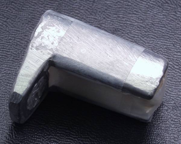
The Terry Dean weights are really slick. They are cast to fit specific models and provide enough weight to keep the nose firmly on the ground. You don't need to guess or mess around stuffing shot, wheel weights, fishing sinkers or nuts and bolts into nooks and crannies and hoping you have enough. Weights for other planes fit in noses or wheel wells and are made for aircraft in 1/72 and 1/48. If you haven't checked these out for yourself, give them a try. He doesn't have a website but you can see and read about them at this link over at Modeling Madness. The weight for this kit fits around the nose wheel well. Note: the light colored area is a chunk of wood inserted in the weight to retain it's shape during shipping and until it's ready to be installed. This worked a treat but Terry apparently no longer does these and it's a pity as it is way better than other methods as far as I'm concerned. See photo below.
Canopy mask set from Eduard (EUEX064)
While the canopies on the P-70 aren't all that complex I hate masking so I opted for one of these. Note: I didn't realize it until I got ready to use it that this set is for the A-20G and only has the masking for the turret and not the earlier gunners canopy.
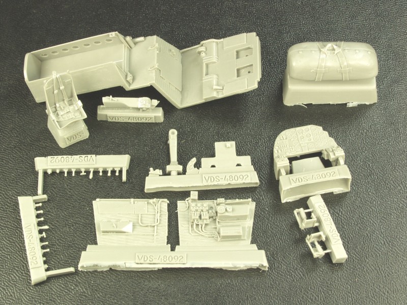
Since this review was originally written Vector released a resin cockpit set that pretty much eliminates the need for the Eduard interior set although it does still contain a few useful items. The Vector number is VDS 48-092. The set contains a replacement floor and compartment behind the pilot, new instrument panel, side walls, control column, seat with molded in harness and belts, throttle console, rudder pedals with brake cylinders, life raft and a lot of knobs and handles. All are molded with the quality Vector is known for. Early test fitting indicates installation will be easy but I'll detail any issues in the build section. See photo below.
I had also purchased the SAC white metal landing gear set but cannot recommend it as it is merely a copy of the kit gear and offers no real advantage of the kit supplied parts.
Links to kit build or reviews
While there are no reviews for the P-70 that I have found there are several for the A-20 which pretty much the same kit. Note the first link is a review / build that uses the Eduard sets above. They can be found here, here, here and here.
References
There is not a lot of info available on the P-70 due to the low numbers built and limited usage. Most of my information was gleaned from "Queen of the Midnight Skies" by Garry R. Pape and Ronald C. Harrison, an excellent book which also covers the other aircraft used by the Army Air Force during WWII including the Beaufighter, P-38, P-61 and Mosquito. There is also some good information in the A-20 book "The Douglas A-20 Havoc, The Ultimate Look" by William Wolf
The Build
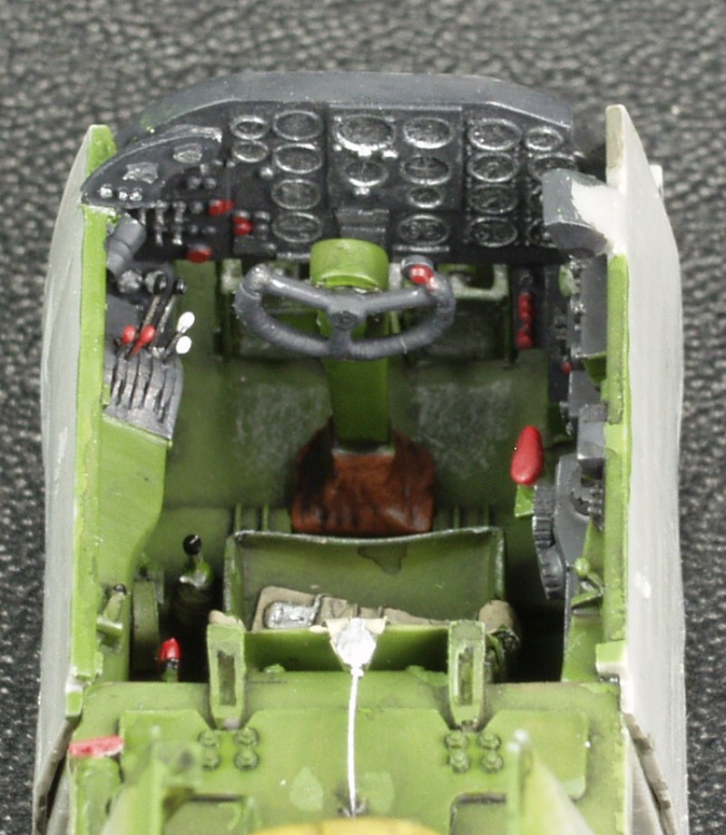
As with most kits this begins with the cockpit and in this case the lovely Vector upgrade set reviewed above. I didn't realize it at the time but there were two parts missing on each of the mold blocks that contain the small levers and the like. I ended up replicating these with some fine gage wire. Everything fit as advertised although I did use a fine razor saw to open up the slots in the throttle quadrant and the other bank of levers just below it to provide a bit deeper slot in which to mount the PE throttle levers. I find this much easier than trying to attach them as a butt joint. I also go back once the glue has set and fill the slots with Future as an extra safety against these coming loose later on. An over coat of flat black eliminates the gloss look. I considered applying instrument decals to the instrument panel but end up just highlighting the detail with a silver pencil and painting the buttons and controls red that were red on a color photo I had. I was glad I did this as once installed the panel sits so far back under the cowl it is very hard to see. Here is what it looks like completed but before the installed in the fuselage.
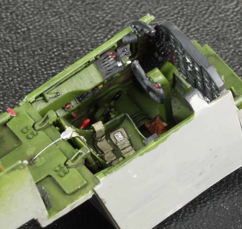
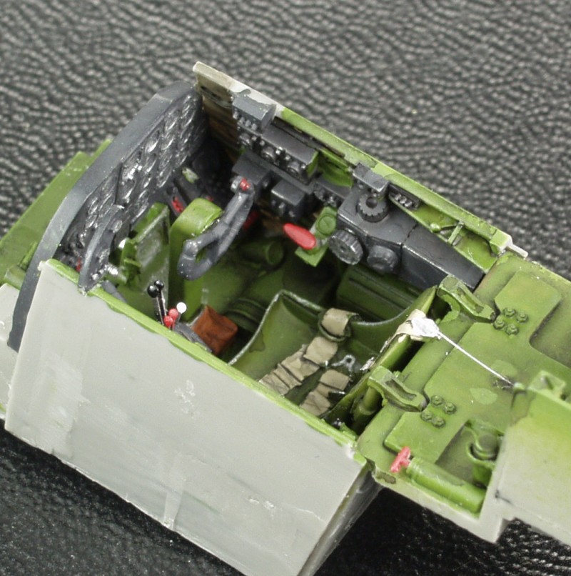
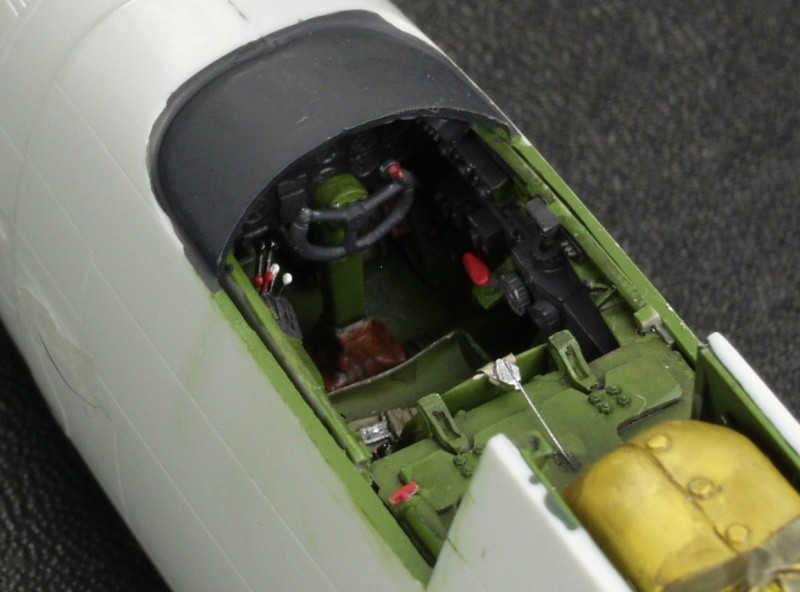
Amazingly this actually fit into the fuselage with almost no plastic needing to be removed. How often does that happen ? I did carve away a small amount of plastic around the bottom forward edge of the kit fuselage where there was a ridge molded in to get the sides of the cockpit to fit tighter to the fuselage at the sills. The next photo shows the pit mounted in the fuselage and shows how little of the instrument panel can be seen.
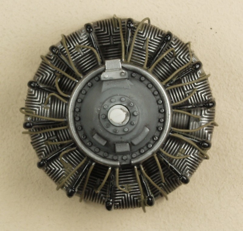
The kit engines were dressed up with an ignition harness
I did add some detail to the radar operators area based on some rough diagrams in the second reference book listed above but didn't get any photos of it prior to installing the canopy over it. Not easy to see but there is a scope an a couple black boxes.
For one reason or another this kit languished on the back burner for a long time until just recently when my interest peaked. It was mostly together just requiring the canopies to be masked and a paint job. I did not take any photos of the finishing steps. The kit was primed with Mr. Surfacer 1200 then over coated with Floquil grimy black. I used up all but a few precious drops of this paint and it's absence will be greatly felt in the future as I have found no really good drop in substitute.
Back to the Night Fighter page
Last updated 2/22/17