
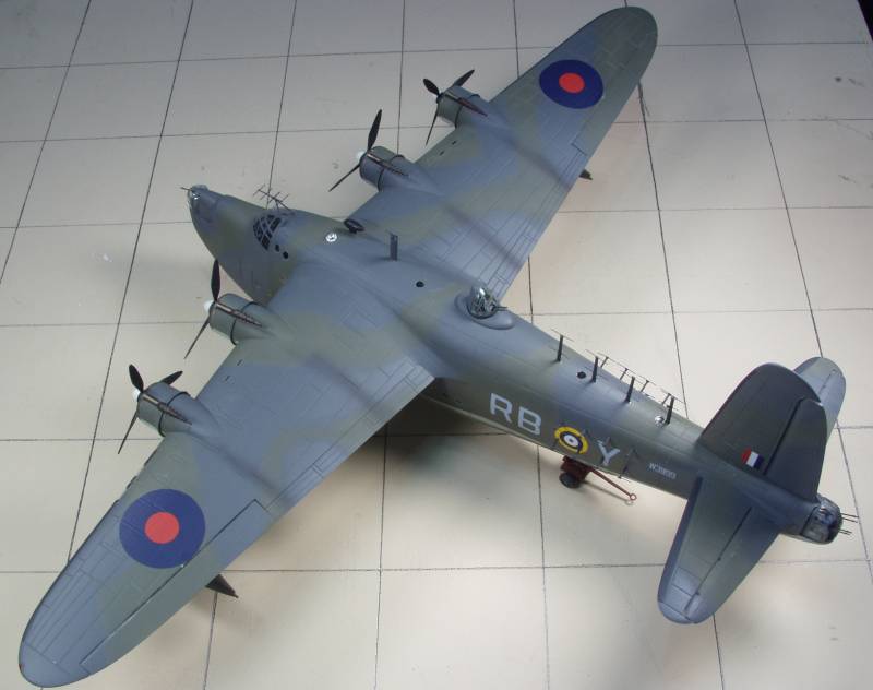
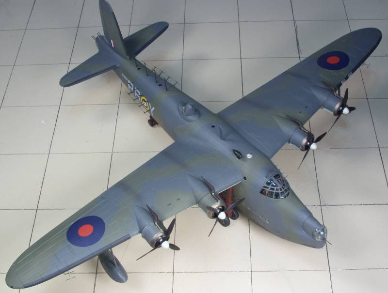
Short Sunderland III

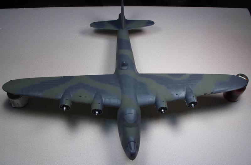
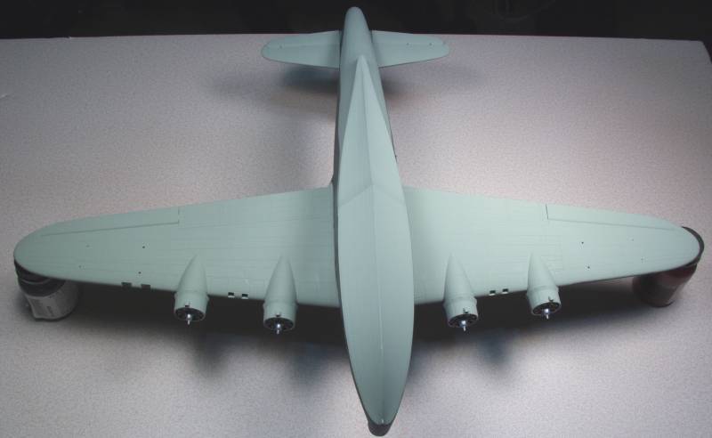
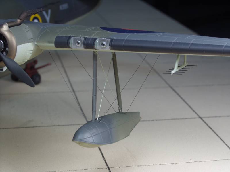
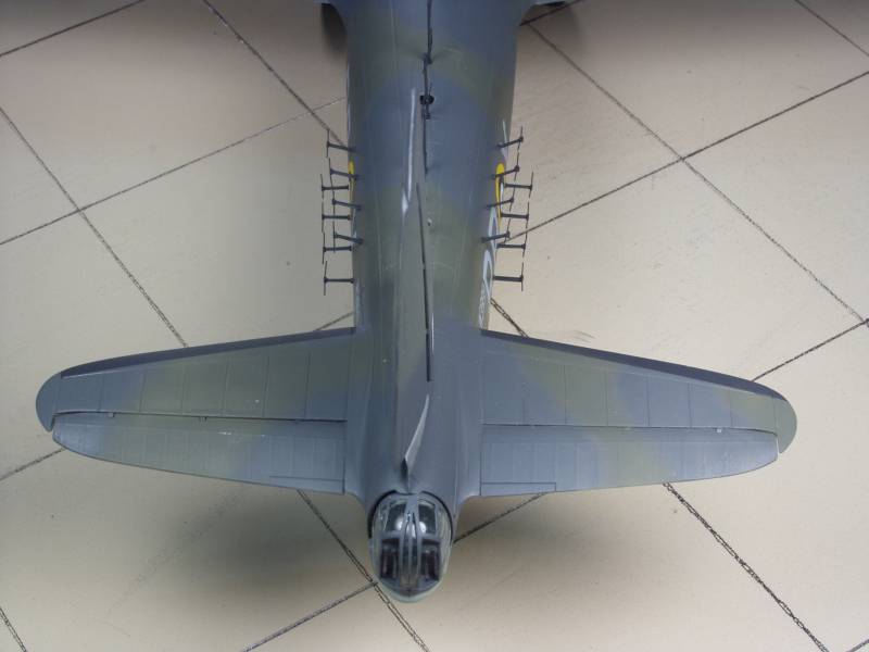
The Sunderland was designed to meet Air Ministry Specification R.2/33 which called for a four engine monoplane flying boat to succeed the long line of biplane types that had served the RAF in the coastal patrol and long range reconnaissance roles for nearly two decades. Short's model S.25 was based on but not a derivative of the C-Class "Empire" Flying Boat airliner. The Sunderland was notable for being the first flying boat to be equipped with power operated bow and tail turrets. The Sunderland competed with the Saunders Roe Saro A.33 which suffered a structural failure as a result of porpoising during taxi tests and effectively eliminated itself from the competition. The RAF's decision to use a powered four gun turret in the tail required some basic changes to the design to accommodated the shift in the center of gravity. This included giving the wings a slight sweep back which resulted in the engines and wing floats to have a slight outward cant.
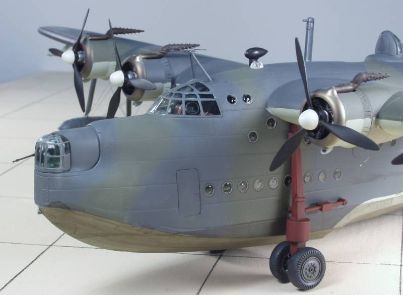
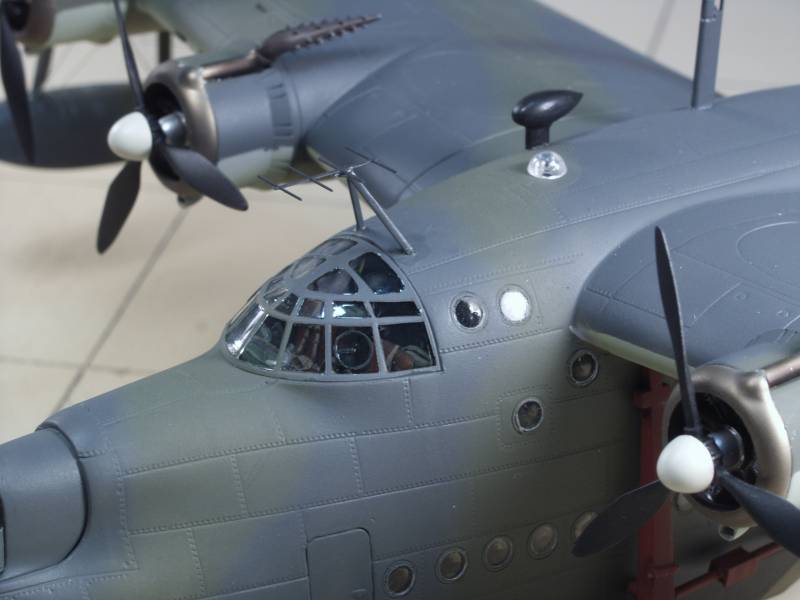
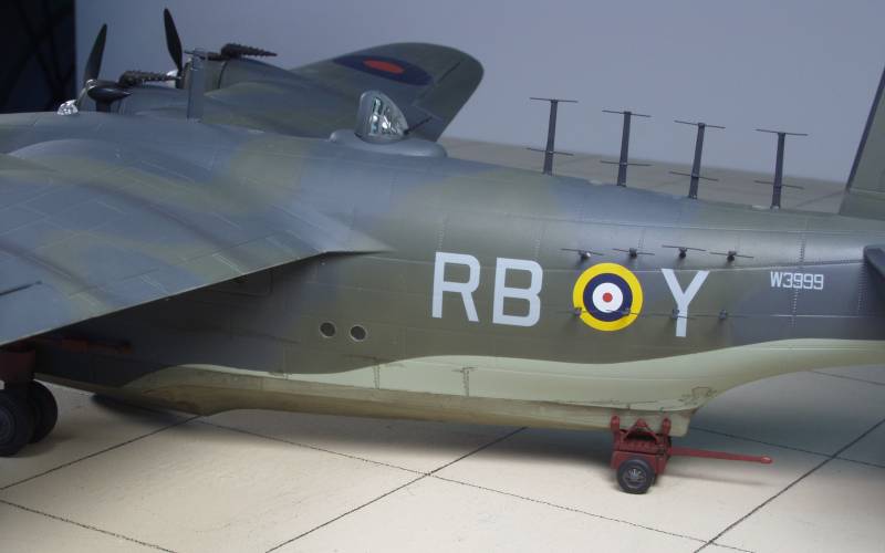
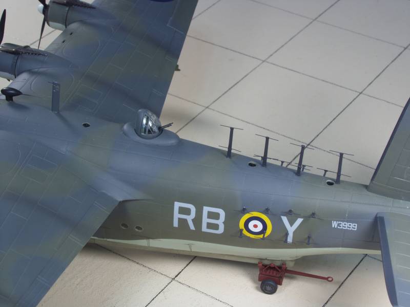
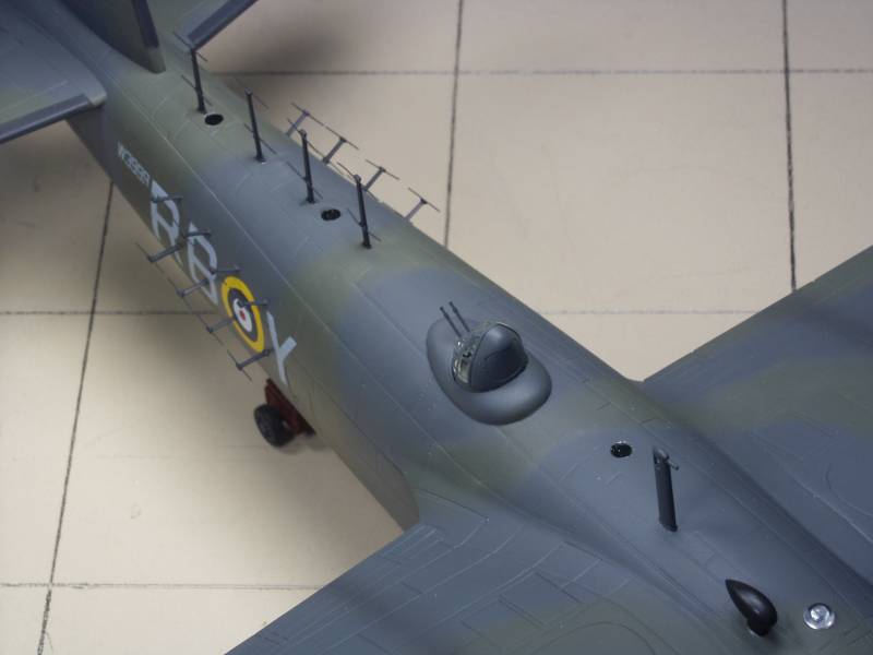
The prototype made its first flight in October of 1937. One interesting feature of the bow turret was that it retracted back into the fuselage to allow space for a crewman to supervise the mooring process. The Sunderland's offensive armament consisted of four 500 lb. bombs or eight 250 lb. bombs carried internally, they were winched out on tracks from the fuselage to a position under the inner wings for deployment. Defensive armament consisted of a Frasier Nash two gun turret in the bow with .303 in. guns, a four gun Frasier Nash four gun turret in the tail with .303 caliber guns and two .303 in. guns firing from two beam positions in the upper hull. It was powered by four Pegasus XXII engines offering 1,010 h.p. for takeoff and 890 h.p at 6,500 feet. Seventy-five Sunderland I's were built which were followed by fifty-eight II's. The II first flew in August of 1941 and differed in having Pegasus XVIII engines rated at 1,050 h.p. for take off and a maximum output of 1,065 h.p. at 1,250 feet. Late production Mk. II's had the beam guns replaced by a power operated dorsal turret with two .303 in. guns. The Sunderland III standardized on the dorsal turret and used the same engines as the Mk. II. It flew in prototype form in in June of 1942. Four-hundred and seven of the Mk. III's had been built by the end of 1943 when production was shifted to the last variant the Mk. V. The Mk. V had four .303 in guns mounted in the forward fuselage and fired by the pilot for use in clearing the decks of U-boats during attack runs. The Mk. V was the first model to switch from the Pegasus engines to R-1830 Twin Wasps of 1,200 h.p. Some Mk. V's had their dorsal turrets replaced by two manually operated 50 caliber guns beam guns. 143 Mk. V's were built bringing the total to 721 of all types.
Sunderland's were given the nickname of "Flying Porcupine" by the Germans and it on more than one occasion proved it could hold its own during attacks by a variety of German aircraft from fighters to the Fw 200 Condor and proved to be a valuable weapon during the battle of the Atlantic.
The Kit
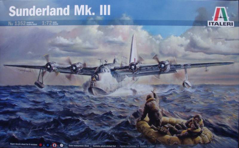
The Italeri Sunderland comes is a fairly large top open tray top box with nicely done artwork. The box is much bigger than needed as there is a lot of left over space inside. Inside the box are three bags of sprues. One has the sprue containing the fuselage halves and this bag also has a bag inside containing the clear parts giving them some extra protection. The other two bags each have two sprue each. In spite of the extra room in the box there were no loose parts and no damaged parts that I could find. The decals were covered with a sheet of thin paper and a fret of PE was enclosed in a separate bag.
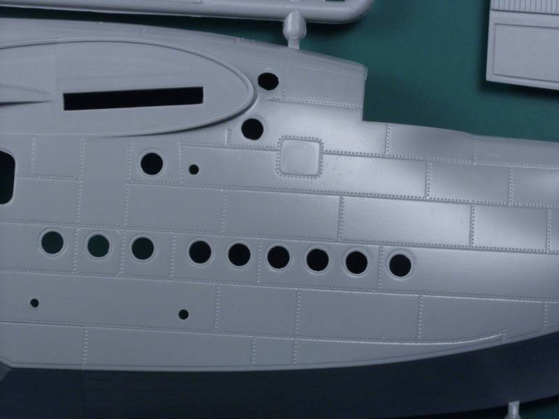
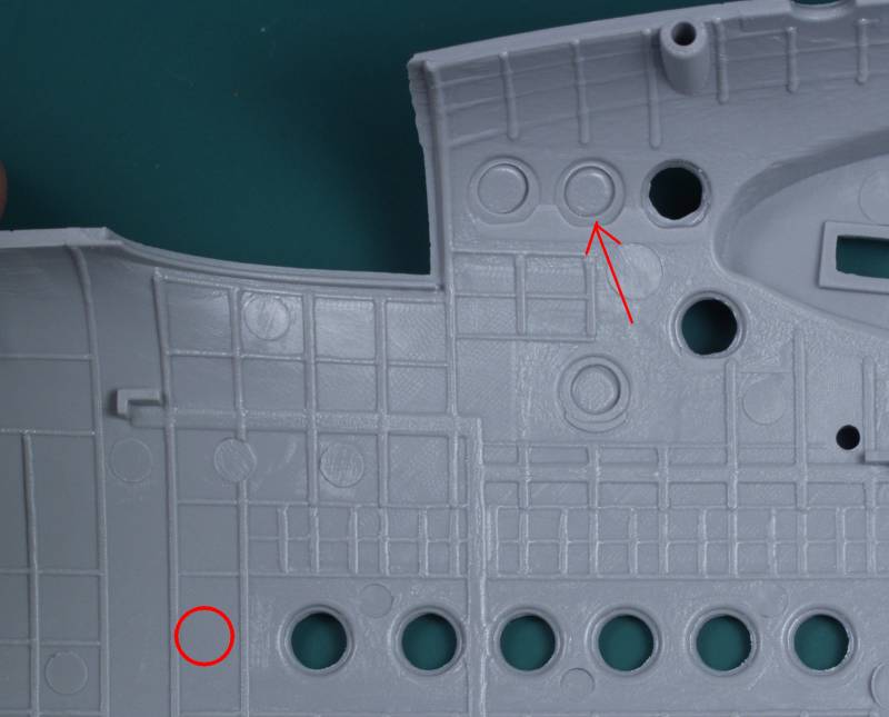
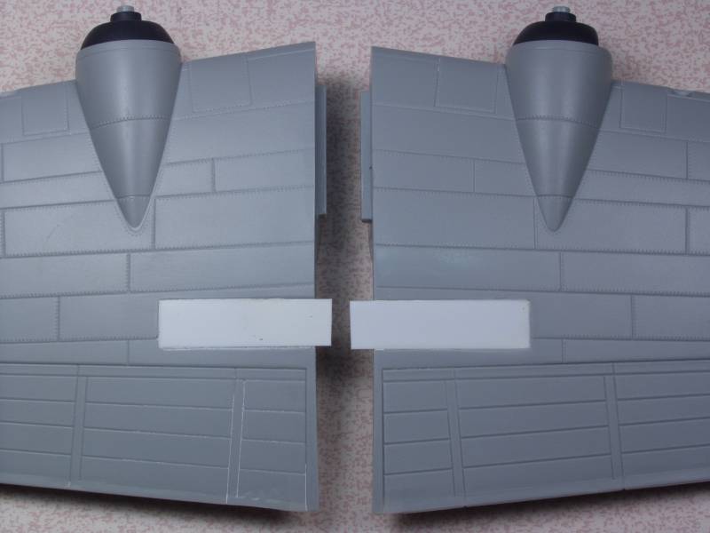
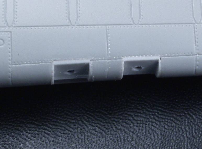
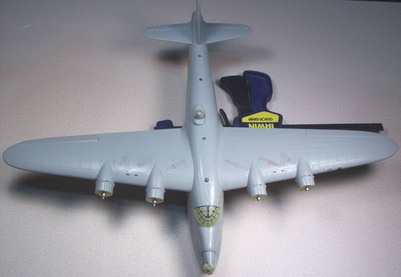
This is the second release of this kit, the first being a Mark I and as such is pretty much the same with a modified hull and different bits to distinguish the Mk I and Mk III. The kit is molded in a light gray plastic and features recessed panel lines and rivets. These seem to be following a trend of late of using way over sized panel lines on 1/72 scale kits. I'm not sure what the deal is unless it has something to do with the conversion of cad data to machine language. The new Roden C-123 and the new Airfix C-47 both feature oversize panel lines. In this case I think the rivet detail, also oversize for the scale, seems to help take away some from the panel lines and I think with a heavy coat of primer and the final paint coats will mostly disguise the issue.
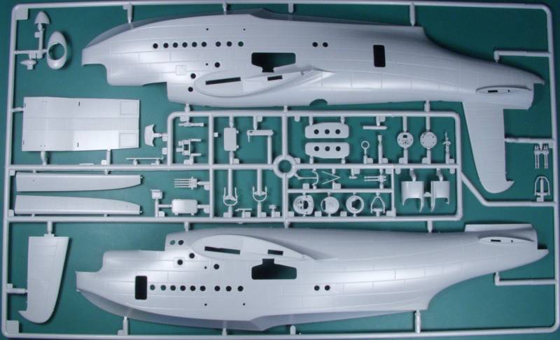
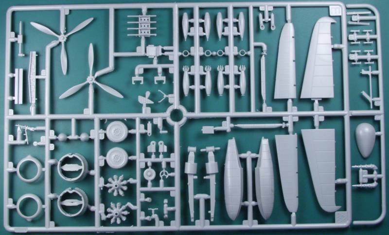
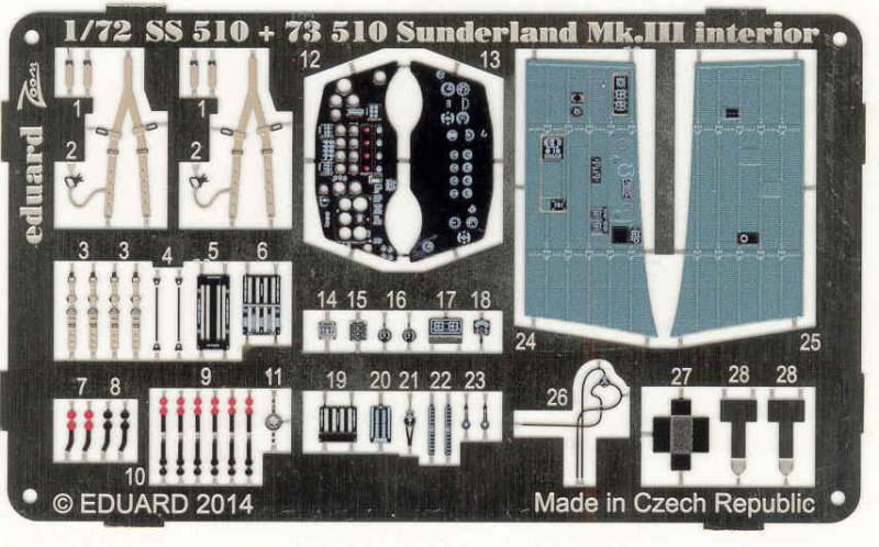
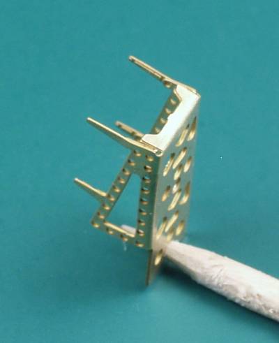
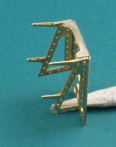
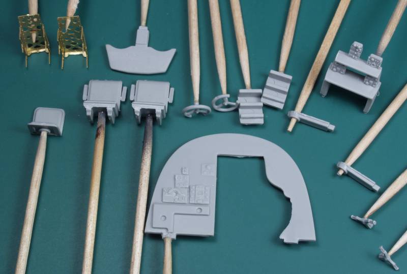
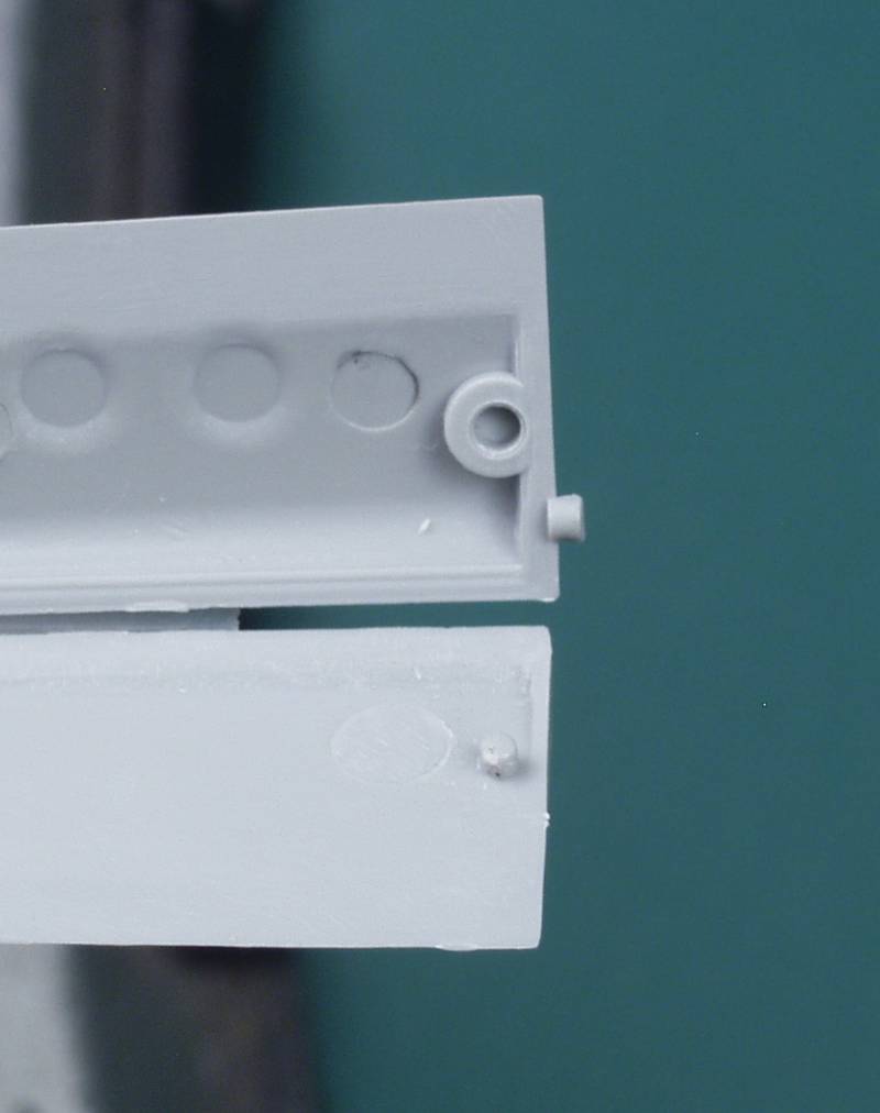
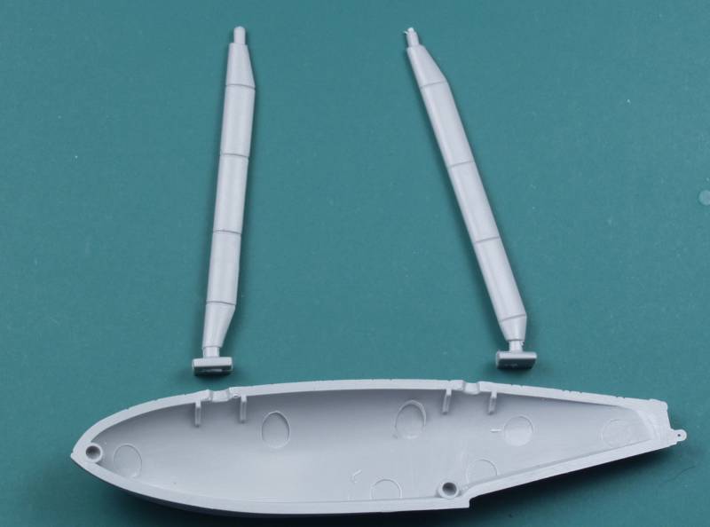
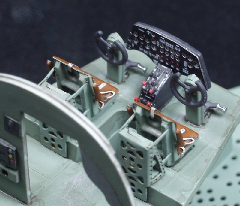
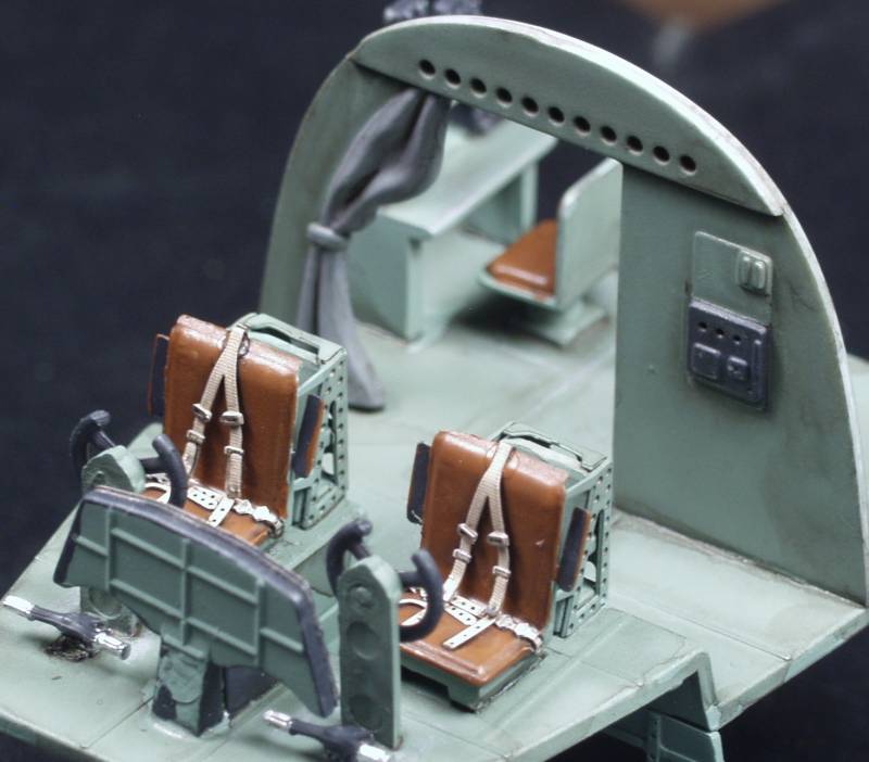
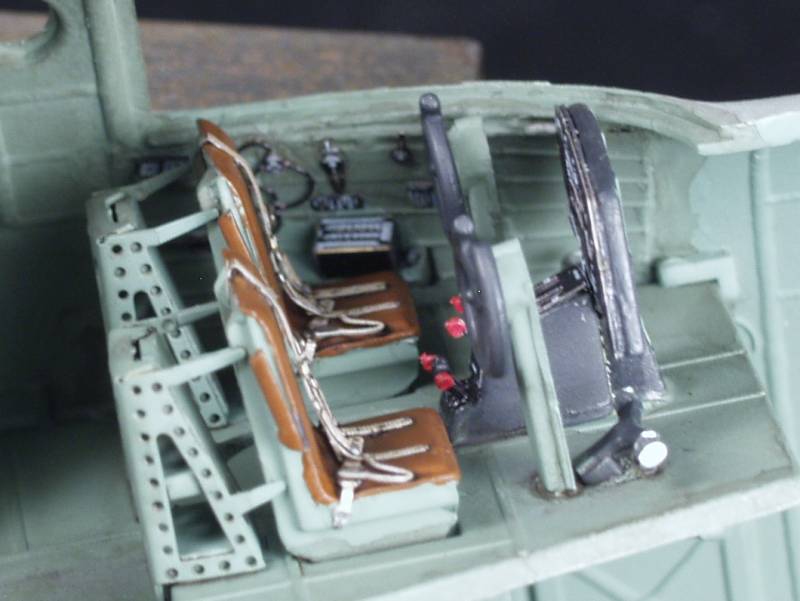
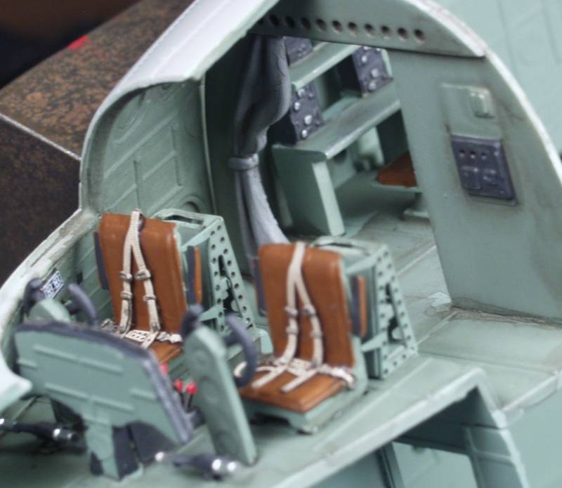
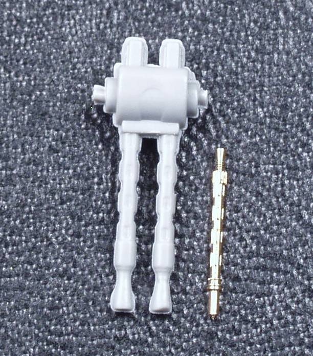
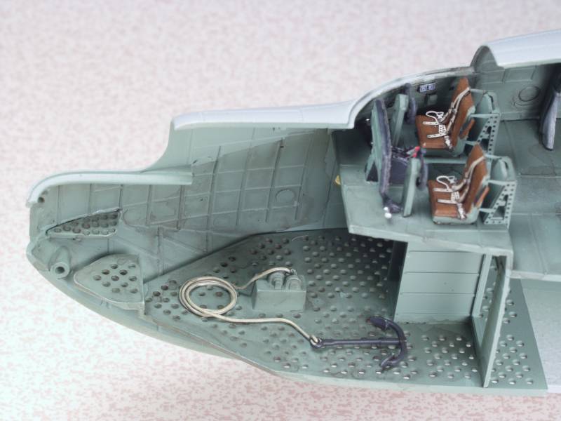
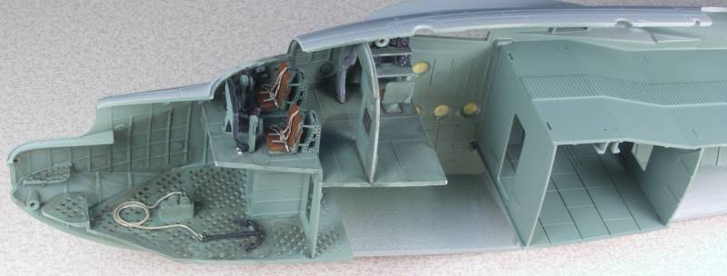
The parts are cleanly molded with only a hint of flash that I could find. Mold parting lines are light and easy to deal with. The sprue attachment point were reasonable in size although a couple on the concave portion of the hull could be hard to deal with. I did not find any sink marks or other surface defects on the exterior surfaces. The control surfaces are all separate and position able and the fabric detail is not overdone as often is the case. The cockpit is well appointed for the scale and the PE fret includes seat belts and harnesses for the pilots seats as well as the structure for the backs of the seats. The instrument panel has a two options, a decal is supplied that can go over the molded on detail or you can remove the molded on detail and use a different decal with the PE instrument panel. The cockpit detail also includes the navigators station behind the pilots area which can be seen through the bulkhead door. The bomb aimers station includes a winch and anchor which will show if you retract the nose turret. The bomb storage section in the mid fuselage is boxed in and included the over head trolley for winching the bombs out. Bomb racks and bombs are provided and they can be positioned under the wings or inside the fuselage.The access doors are separate and can be positioned open. There are also separate crew access doors for and aft on the fuselage that can be positioned either open or closed. The turrets have enough detail to satisfy most. The kit comes with nicely detailed beaching gear and tail trolley. The engine detail is pretty much standard for the scale. The engine faces have holes molded in for the exhaust stubs that connect to the forward exhaust collector ring but these are not supplied. They could be added using small diameter wire of solder but it would be tedious at best. Diagrams are provided for the wire bracing on the wing floats. Lets take a look at the sprues.
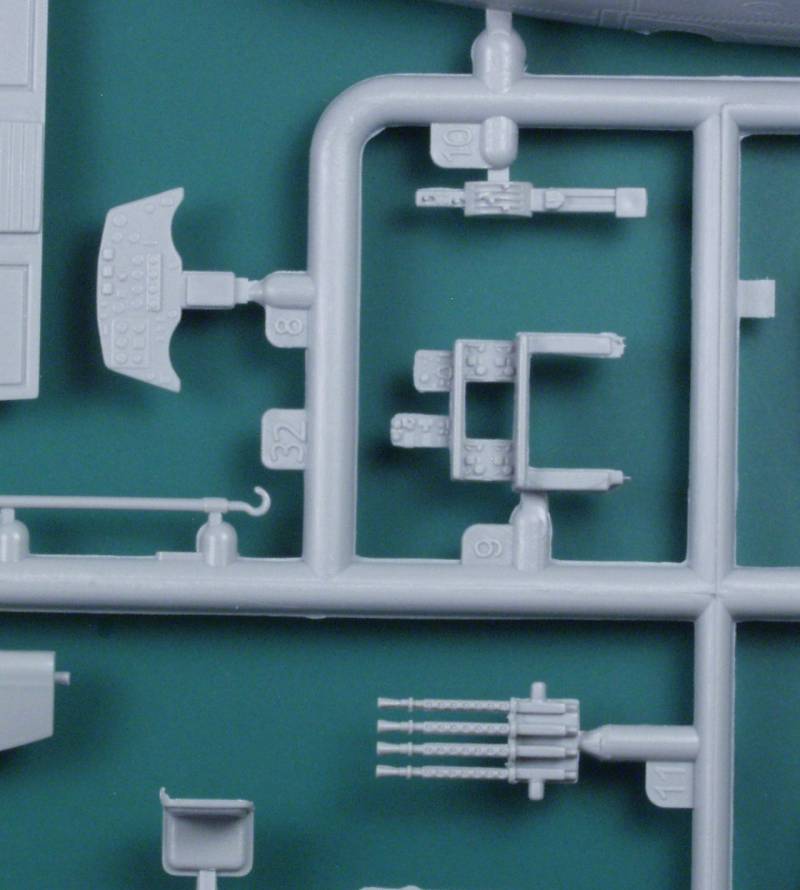
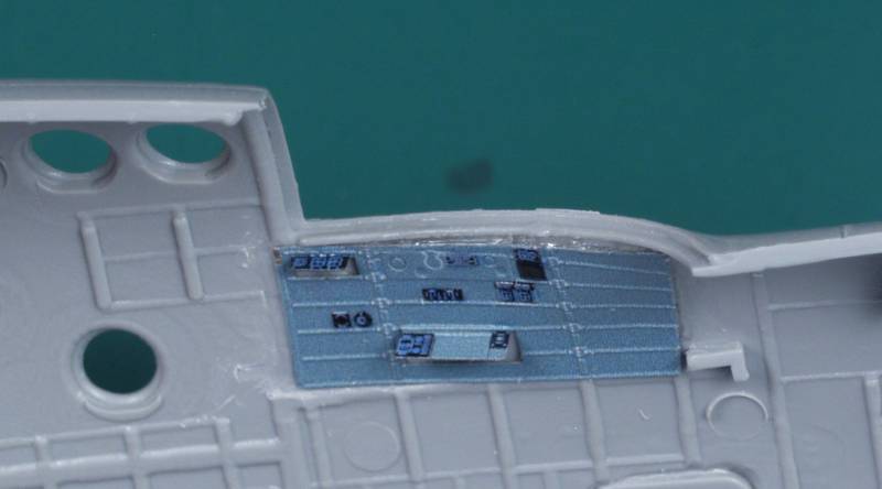
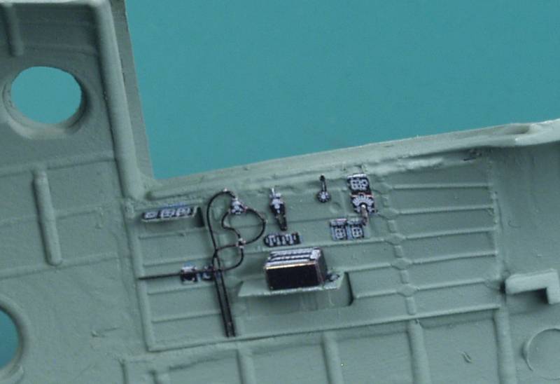
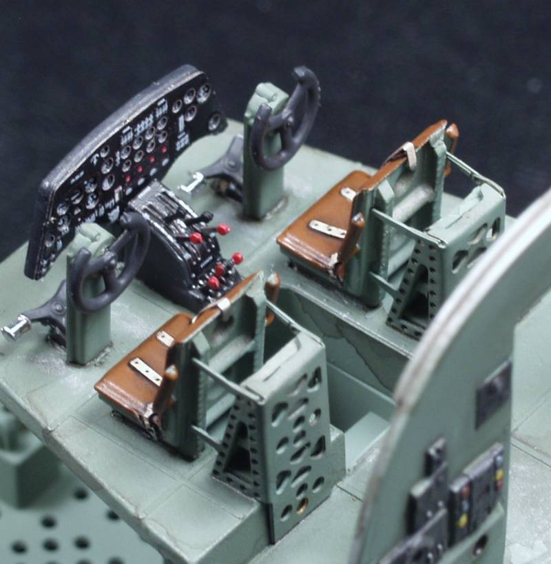
This close up shows the instrument panel, overhead console, navigators instruments and machine guns.
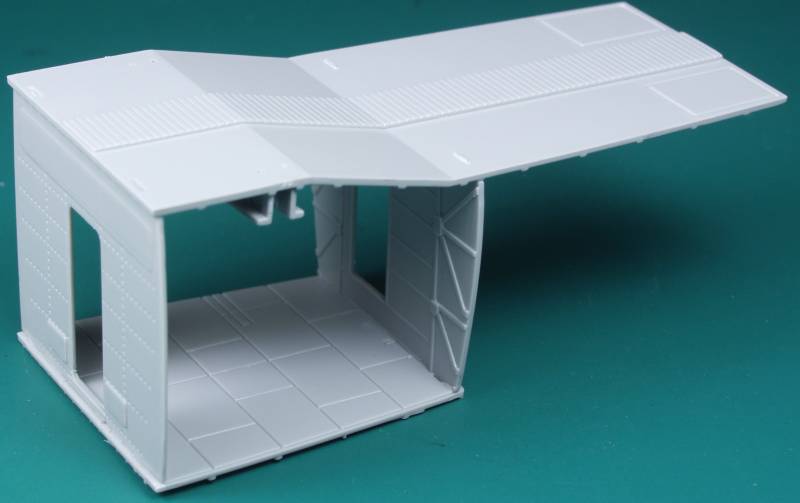
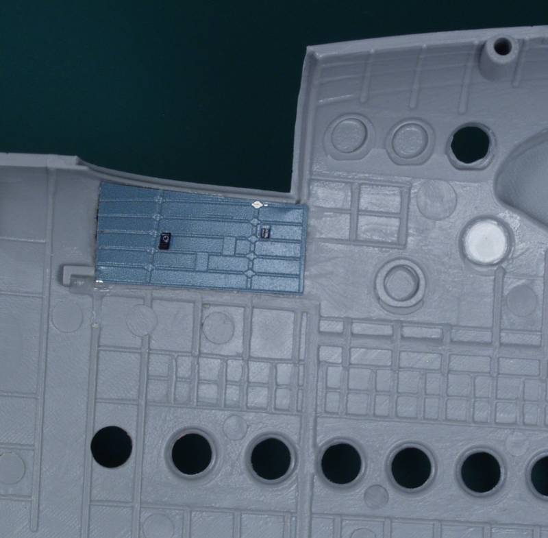
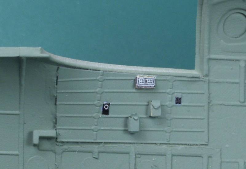
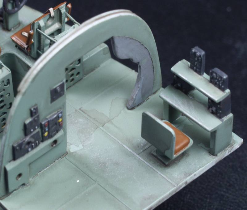
A look at the interior detail. There are ejector pin marks but the vast majority won't be seen when every thing is closed up.
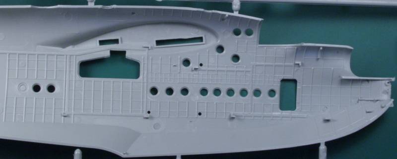
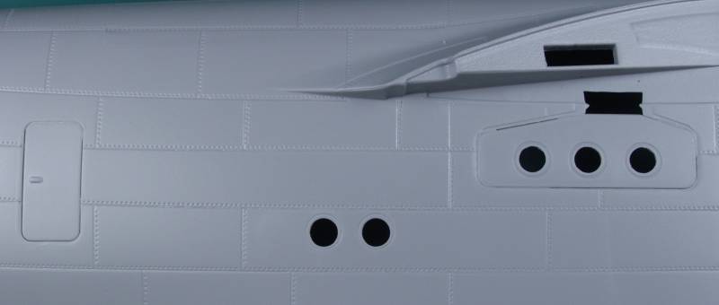
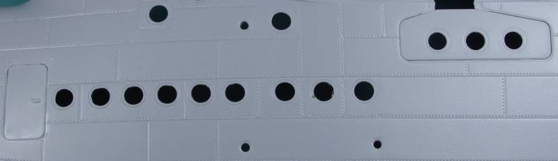
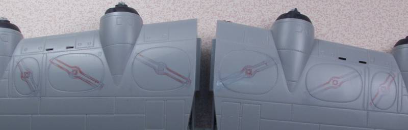
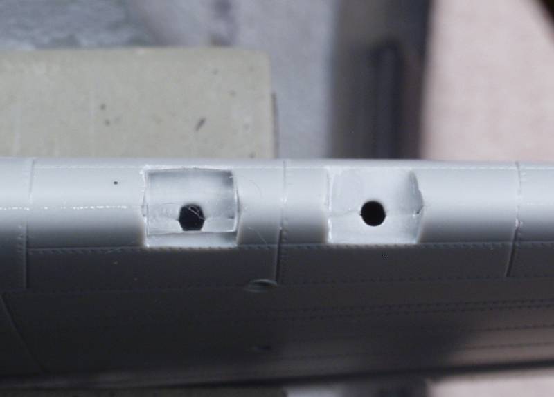
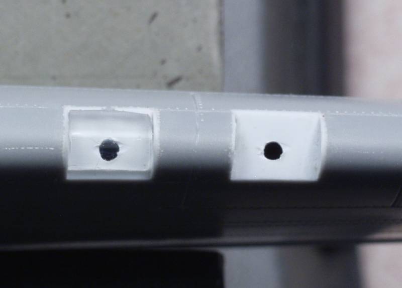
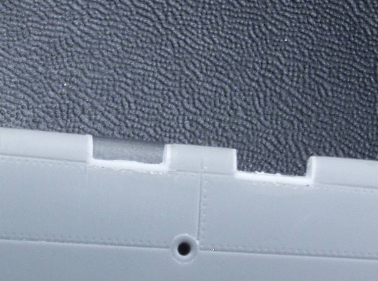
A close up of the surface detail.
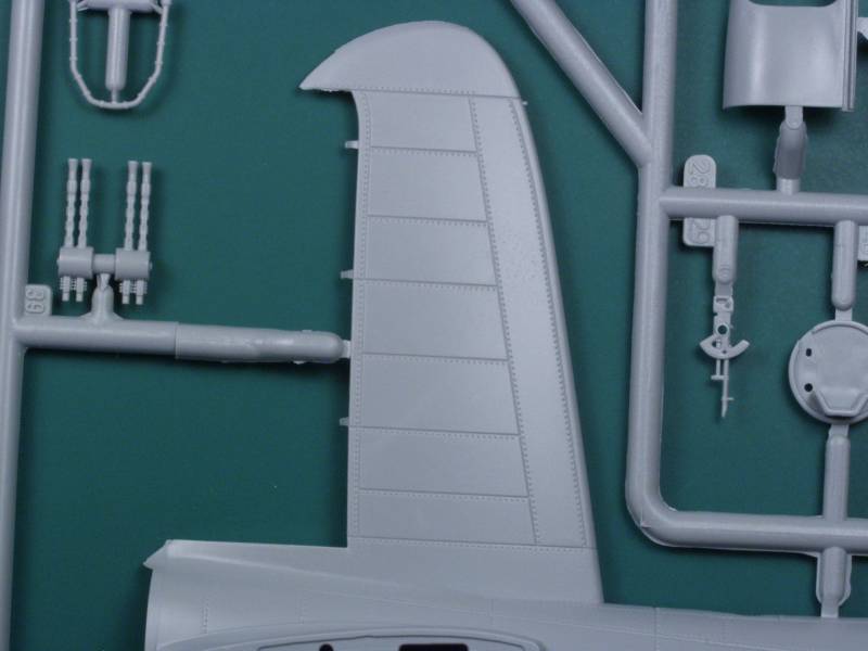
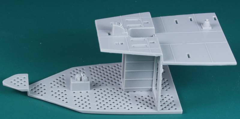
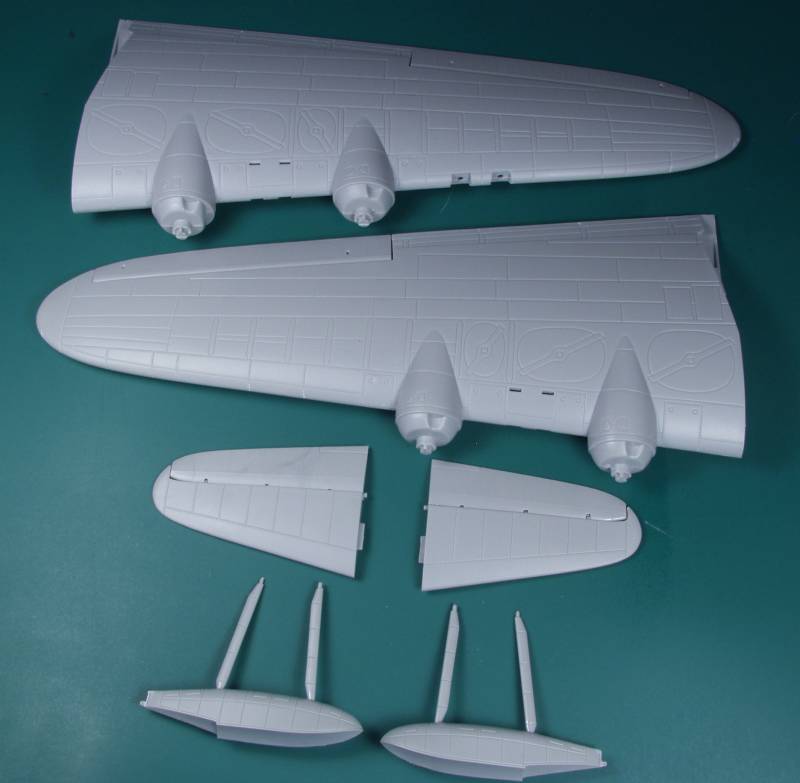
The wing sprues.
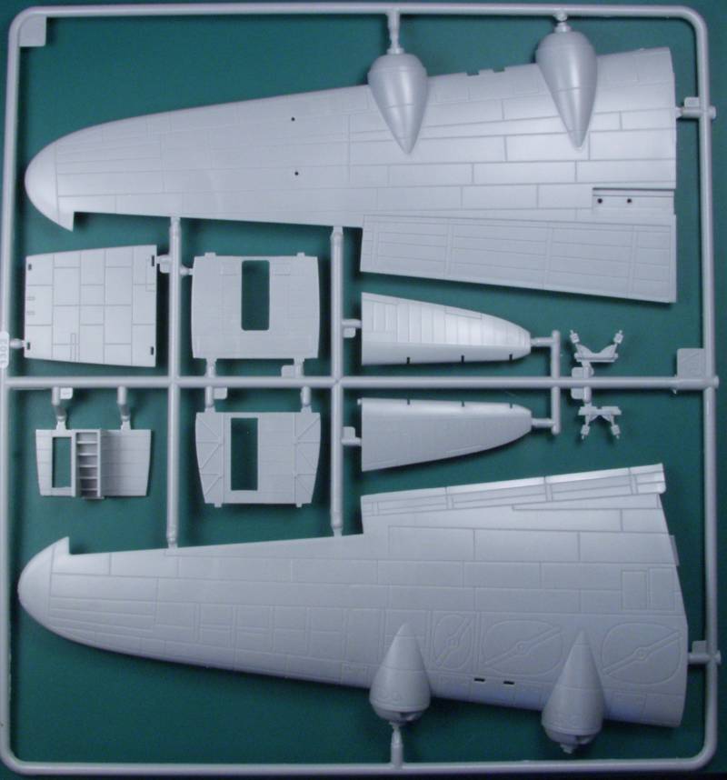
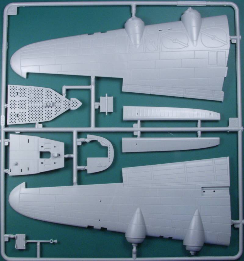
There are two of these sprues
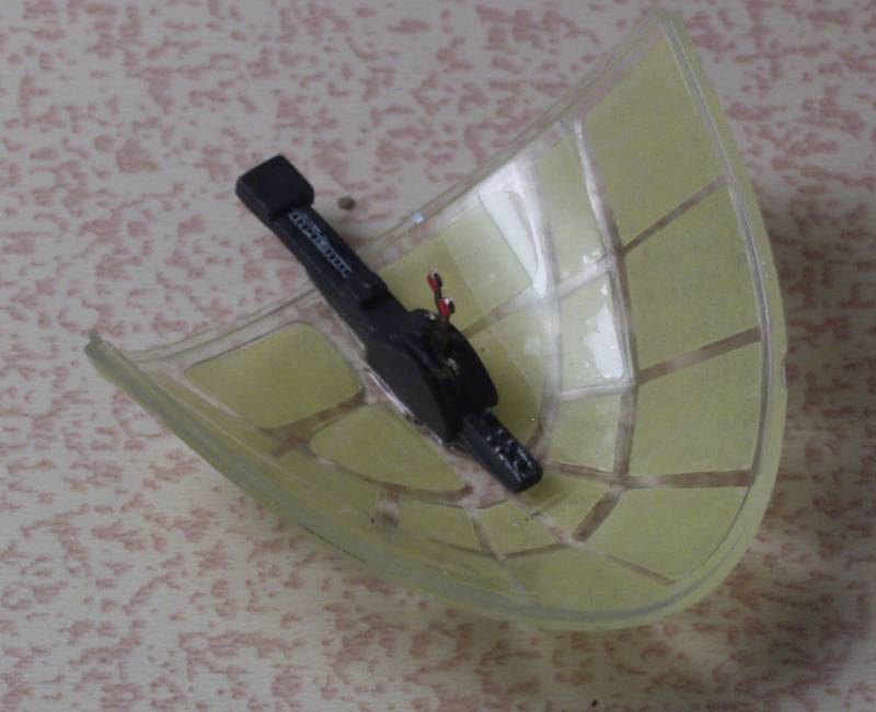
The clear parts are reasonably clear and a bit thick and they do have some distortion in them, especially the turrets. Most of the round windows have a bubble or sink mark in them. I'm not sure at this point how distracting that will be. The main cockpit enclosure features something I have not seen before. It has a flange around the perimeter that fits into a slot in the fuselage. It is intended to installed before the fuselage is assembled to provide a nice gap free assembly. To be this looks like it could be troublesome if one gets glue on it. It can be installed later if you remove the flange from the rear of the enclosure which is what I will most likely do.
![]()
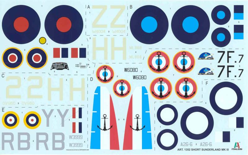
The decals look great, thin and in register, the colors look good and there is almost no excess clear film around the outside of them. They were done by Cartograph so I have no reason to believe they will have any issues. The sheet provides markings for six aircraft, three RAF, one SEAC, one French and one RAAF.
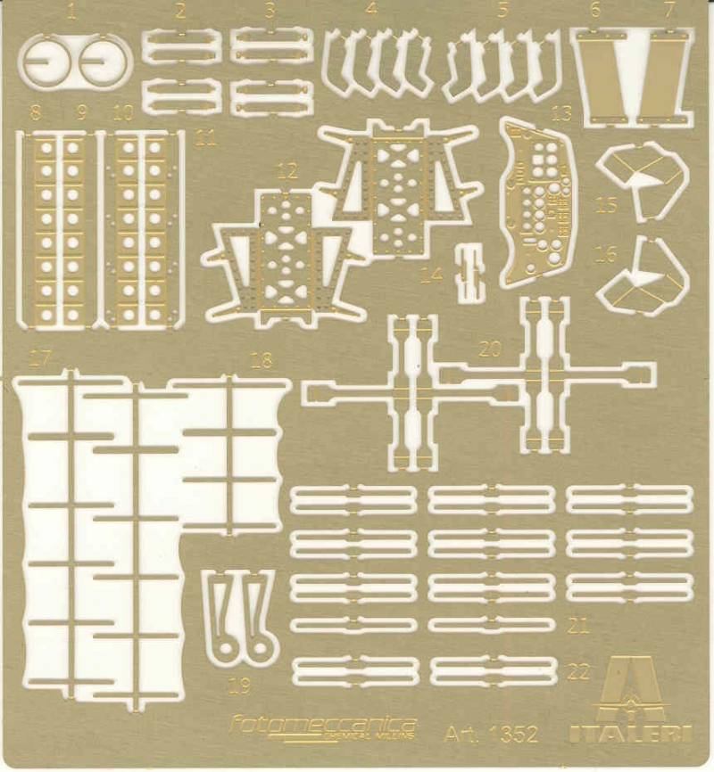
The photo
etch includes seat frames, harnesses and
belts for the pilots, bomb racks, instrument panel, wiper blades and
circular clear view panels for the main cockpit glass, support brackets
for the hedgehog exhausts, a couple of turret parts and a set of the
yagi array antennas. Over all a nice selection.
Links to kit build or reviews
References

Updated 2/1/15